Supercharge Your Innovation With Domain-Expert AI Agents!

Network analyzer applying loss compensation using port extensions and method of operation

a network analyzer and loss compensation technology, applied in the direction of resistance/reactance/impedence, testing circuit, instruments, etc., can solve the problems of reducing the accuracy of the measurement of a dut using the test fixture, properly functioning parts to fail the insertion loss test, and reducing the accuracy of the measurement of the dut, etc., to achieve a greater degree of accuracy in the calculation

Inactive Publication Date: 2006-04-06
AGILENT TECH INC
View PDF1 Cites 4 Cited by
  • Summary
  • Abstract
  • Description
  • Claims
  • Application Information

AI Technical Summary

Benefits of technology

[0006] Additional representative embodiments are directed to systems and methods for automatically calibrating a network analyzer that includes loss compensation port extension functionality. Specifically, S11 measurements of a known reflection are made from which phase and amplitude references can be generated. “S11 measurements” refer to measurements made by a network analyzer using a scattering parameter model where “S11” refers to the ratio of a reflected signal to an incident signal on the same port. The known reflection may result from an open circuit (e.g., omitting the DUT from the test fixture) and / or a short circuit. Processing of the measurement data may be performed to account for errors in the amplitude response that result from poor source / PCB match of the test set-up. The processing enables a greater degree of accuracy in the calculation of the loss presented by the various port connections to the test fixture.

Problems solved by technology

However, the use of network analyzers and test fixtures to perform such measurements presents difficulties.
The variations may result from PCB layout constraints, manufacturing process limitations, and / or other reasons.
The variations between ports may cause the loss to vary between the port thereby reducing the accuracy of the measurements of a DUT using the test fixture.
The amplitude loss in the test fixture may cause a properly functioning part to fail insertion loss tests.
The amplitude loss can also make matching measured results to model predictions difficult.
Accordingly, it is often the case that the requirements for de-embedding a test fixture are difficult and are often not practical in normal manufacturing environments.

Method used


Image

  • Network analyzer applying loss compensation using port extensions and method of operation
  • Network analyzer applying loss compensation using port extensions and method of operation
  • Network analyzer applying loss compensation using port extensions and method of operation

Examples


Embodiment Construction

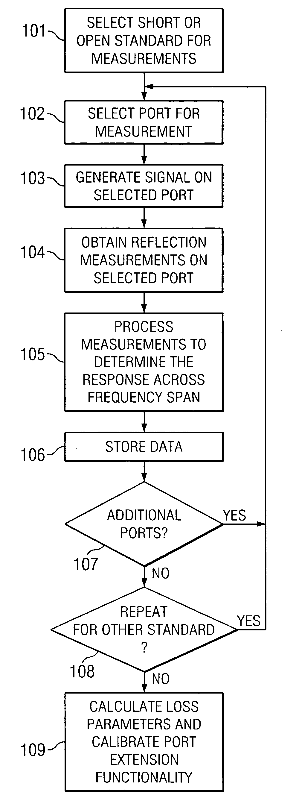
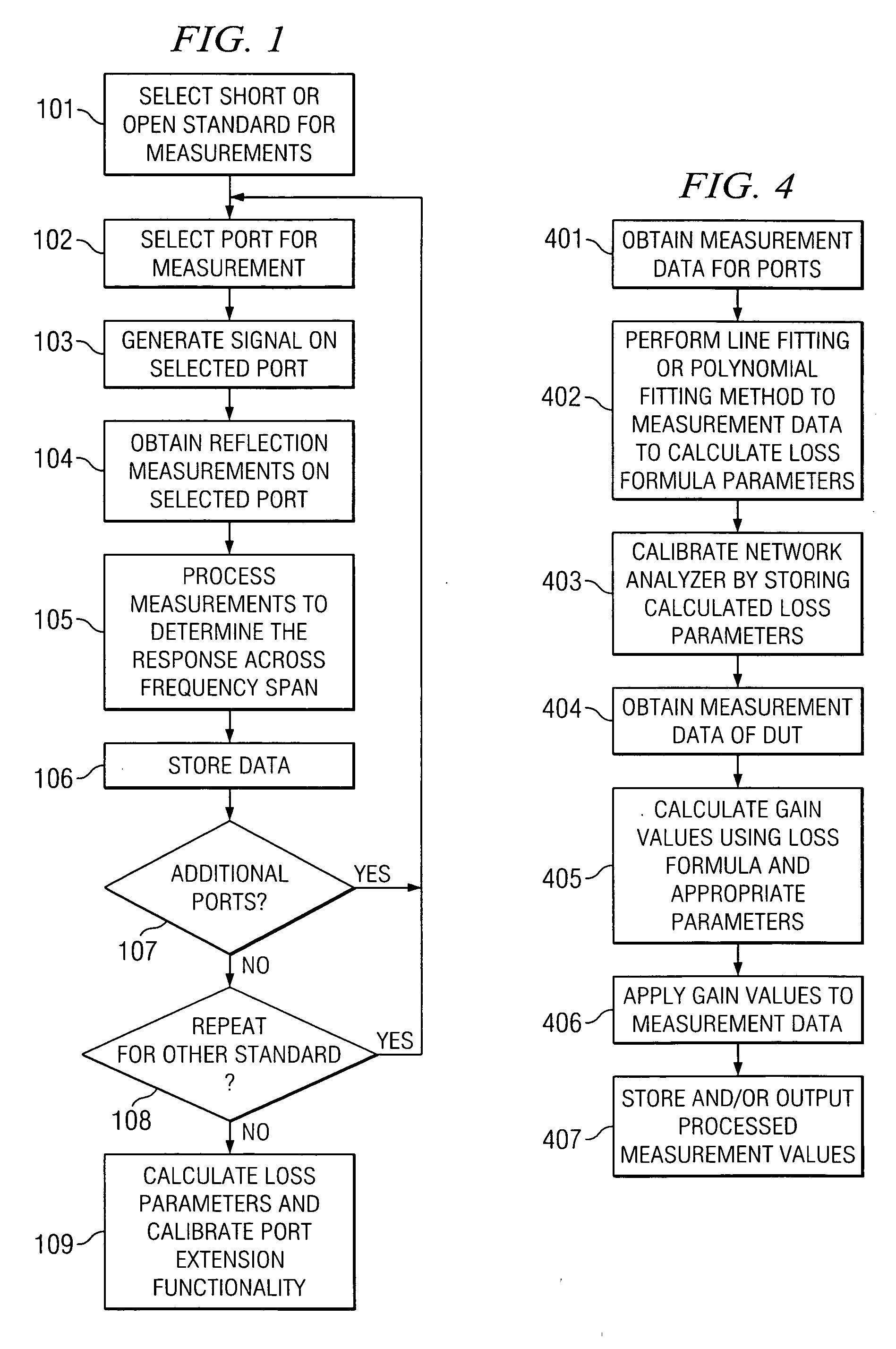
[0013] Known port extension functionality refers to processing performed by a network analyzer to correct the delay resulting from the extension of a port of the network analyzer to a DUT using, for example, a test fixture. Known port extension applies a relatively simple linear model of phase response of a test fixture to correct measurement data in real-time during operation of a network analyzer. Known port extension functionality does not account for loss introduced by the test fixture. Specifically, the amplitude response of a test fixture is substantially more complicated than the linear model used for phase compensation and, hence, known port extensions are not capable of applying known amplitude correction techniques to measurement data in real-time.

[0014] Some representative embodiments provide port extension functionality in a network analyzer to correct for the amplitude response of a test fixture. Specifically, some representative embodiments employ a formula that model...


PUM


Abstract

In one embodiment, a method of operating a network analyzer, comprises applying a stimulus signal on at least one port of the network analyzer for provision to a device under test (DUT) within a test fixture coupled to the network analyzer; generating measurement data from the DUT in response to the stimulus signal on at least one port of the network analyzer; and generating an amplitude response of the DUT across a frequency range, wherein a port extension module of the network analyzer automatically applies loss compensation to the amplitude response in a manner that is non-linearly related to frequency according to at least one controllable parameter.

Description

TECHNICAL FIELD [0001] The present application is generally related to calibrating network analyzers to perform measurements using test fixtures. BACKGROUND OF THE INVENTION [0002] Network analyzers are devices that are used to determine the radio frequency (RF) characteristics of various devices under test (DUTs). In many situations, a DUT is a relatively small component designed to interface with a trace contact point on a printed circuit board (PCB). Many network analyzers typically utilize an interface adapted to receive a coaxial coupling. To test a DUT designed to be employed on a PCB using such a network analyzer, a test fixture is often employed. A test fixture is generally a specialized device that is adapted to readily accept a DUT and that electrically couples the DUT to one or several ports of a network analyzer. [0003] For many DUTs (such as balanced filters, baluns, balanced amplifiers, etc.), the pertinent performance measurements depend upon both the magnitude and ph...

Claims


Application Information

Patent Timeline
IPC IPC(8): G06F19/00G01R27/28G01R35/00
CPCG01R27/28G01R35/005
Inventor DUNSMORE, JOELBENDER, DOUGBLACKHAM, DAVID
Owner AGILENT TECH INC
Features
  • R&D
  • Intellectual Property
  • Life Sciences
  • Materials
  • Tech Scout
  • Unparalleled Data Quality
  • Higher Quality Content
  • 60% Fewer Hallucinations
Learn More