Laser beam processing machine
- Summary
- Abstract
- Description
- Claims
- Application Information
AI Technical Summary
Benefits of technology
Problems solved by technology
Method used
Image

Examples
first embodiment
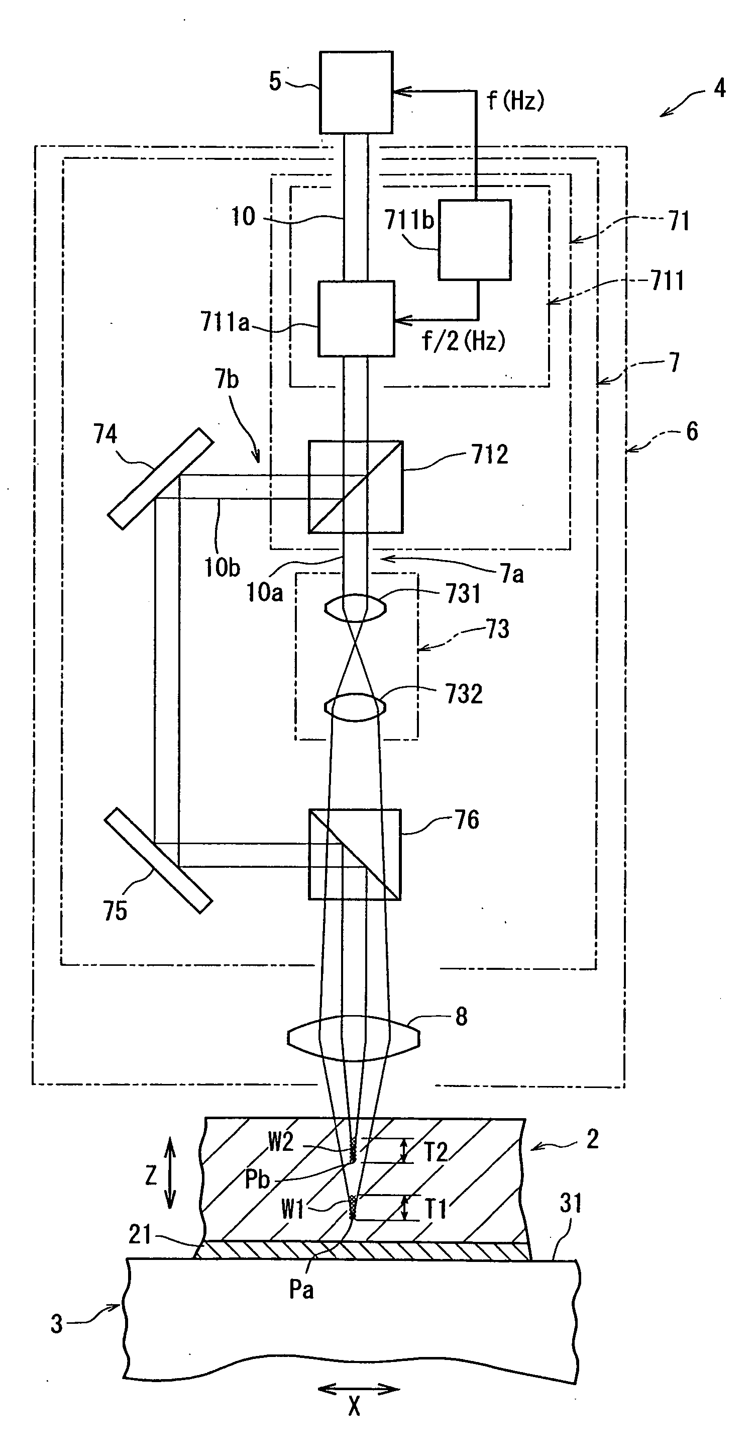
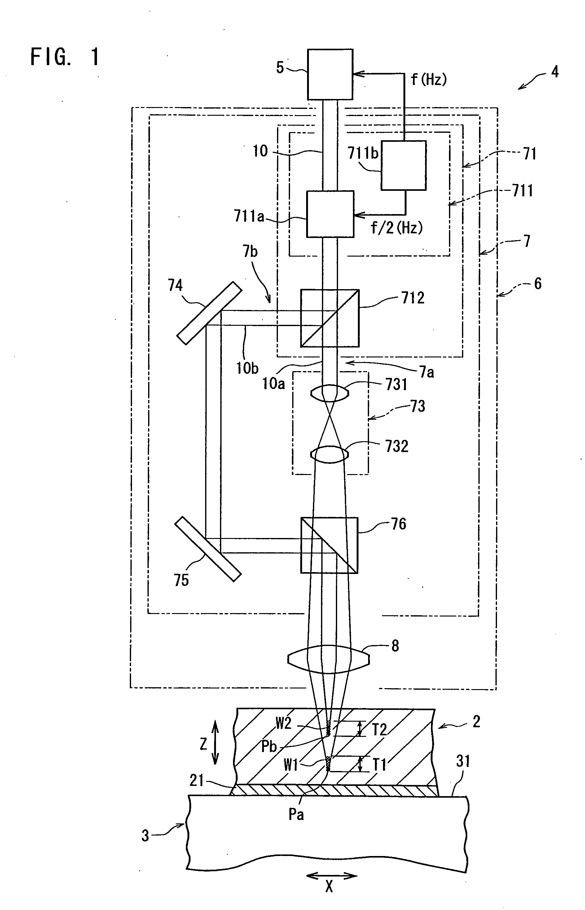
[0021]FIG. 1 is a schematic diagram of a laser beam processing machine constituted according to the present invention. The illustrated machine comprises a chuck table 3 for holding a wafer 2 as a workpiece and a laser beam application means denoted by 4.
[0022] The chuck table 3 comprises an adsorption chuck 31 made from a porous member or having a plurality of suction holes or grooves, and the adsorption chuck 31 is communicated with a suction means that is not shown. Therefore, a protective tape 21 affixed to the side of a surface on which a circuit is formed, of the wafer 2 as the workpiece is placed on the adsorption chuck 31, and the wafer 2 is suction-held on the chuck table 3 by activating the suction means that is not shown. The thus constituted chuck table 3 is so constituted as to be moved in a processing-feed direction indicated by an arrow X in FIG. 1 by a processing-feed means that is not shown. Therefore, the chuck table 3 and the laser beam application means 4 can move...
second embodiment
[0040] A description is subsequently given of the laser beam application means 4 with reference to FIG. 3.
[0041] The laser beam application means 4 shown in FIG. 3 differs from the laser beam application means 4 shown in FIG. 1 in that the focusing point depth displacing means 73 is arranged in the second path 7b. This focusing point depth displacing means 73 is composed of one convex lens 733 and is interposed between the beam splitter 712 and the first mirror 74. Since the constitution of the laser beam application means 4 shown in FIG. 3 is substantially the same as that of the laser beam application means 4 shown in FIG. 1 except for the focusing point depth displacing means 73, the same members are given the same reference symbols and their descriptions are omitted.
[0042] In the laser beam application means 4 shown in FIG. 3, the vertically polarized light and the horizontally polarized light divided by the modulator 711a of the polarization conversion means 711 alternately ar...
third embodiment
[0044] A description is subsequently given of the laser beam application means 4 with reference to FIG. 4.
[0045] The laser beam application means 4 shown in FIG. 4 differs from the laser beam application means 4 shown in FIG. 1 in the path distribution means for distributing a pulse laser beam oscillated by the pulse laser beam oscillation means 5 to the first path 7a and the second path 7b alternately. That is, the path distribution means 72 in the embodiment shown in FIG. 4 is composed of a modulator 721 for dividing a pulse laser beam oscillated by the pulse laser beam oscillation means 5 into two different paths alternately and a pulse generator 722 for providing a sync signal for setting are petition frequency (f) to the pulse laser beam oscillation means 5 and a sync signal having a frequency (f) / 2 to the modulator 721. As the modulator 721 is used a modulation element making use of an acoustic-optic effect in the illustrated embodiment. By providing this path distribution mea...
PUM
| Property | Measurement | Unit |
|---|---|---|
| Angle | aaaaa | aaaaa |
| Frequency | aaaaa | aaaaa |
| Acoustic properties | aaaaa | aaaaa |
Abstract
Description
Claims
Application Information
 - Generate Ideas
- Intellectual Property
- Life Sciences
- Materials
- Tech Scout
- Unparalleled Data Quality
- Higher Quality Content
- 60% Fewer Hallucinations
Browse by: Latest US Patents, China's latest patents, Technical Efficacy Thesaurus, Application Domain, Technology Topic, Popular Technical Reports.
© 2025 PatSnap. All rights reserved.Legal|Privacy policy|Modern Slavery Act Transparency Statement|Sitemap|About US| Contact US: help@patsnap.com