Electron beam irradiating method and manufacturing method of magnetic recording medium

a technology of electromagnetic radiation and manufacturing method, which is applied in the field of electromagnetic radiation irradiation method and magnetic recording medium manufacturing method, can solve the problems of overexposure, complicated manufacturing step, and thick circumferential direction

Inactive Publication Date: 2006-04-13
KK TOSHIBA
View PDF5 Cites 66 Cited by
  • Summary
  • Abstract
  • Description
  • Claims
  • Application Information

AI Technical Summary

Benefits of technology

[0016] The present invention has been made in view of these circumstances, and an object thereof is to provide an electron beam irradiating method which allows formation of a fine pattern and a manufacturing method of a magnetic recording medium using the electron beam irradiating method.

Problems solved by technology

However, the publication does not describe a technique about the electron beam lithography.
Otherwise, when one of the user data track region and the servo region is added to the other later, it is difficult to position the both regions, which result in necessity for a complicated manufacturing step.
However, in case that lines in a circumferential direction and in a radial direction are exposed at a cutting track pitch “a” in the radial direction, there is such a problem that, when the cutting track pitch “a” is small, over-exposure tends to occur in a line extending in a radial direction, as shown in FIG. 14, and when the cutting track pitch “a” is large, a line in the circumferential direction becomes thick, if the line is obtained through a plurality of exposures.
When a line in the circumferential direction is formed through only one exposure, namely, one round exposure in order to make the line thin, there occurs such a problem that lack in exposure amount occurs in a line extending in a circumferential direction or excess in exposure amount occurs in a line extending in a radial direction, which results in impossibility in formation of a fine pattern.
In a pattern with a poor rectangular shape, there may occur such a problem that imprinting can not be conducted with an excellent contrast or a high pressure is required at a time of imprinting.

Method used


Image

  • Electron beam irradiating method and manufacturing method of magnetic recording medium
  • Electron beam irradiating method and manufacturing method of magnetic recording medium
  • Electron beam irradiating method and manufacturing method of magnetic recording medium

Examples


embodiments

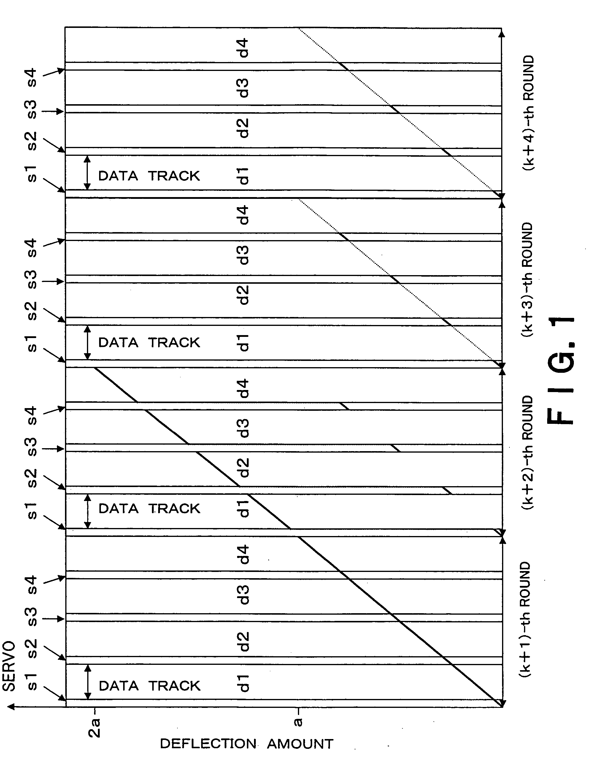
[0038] An electron beam irradiating method according to an embodiment of the present invention will be explained with reference to FIGS. 1 to 4F. An electron beam irradiating method according to the embodiment is used for a manufacturing method of a magnetic recording medium of a discrete type. As shown in FIG. 8, for example, the electron beam irradiating method is implemented using an electron beam irradiating apparatus of a stage continuous moving system provided with a moving mechanism for moving a stage in one horizontal direction and a rotating mechanism for rotating the stage. In the embodiment, it is desirable that the stage is rotated at a constant linear velocity in order to be kept an exposure amount even.

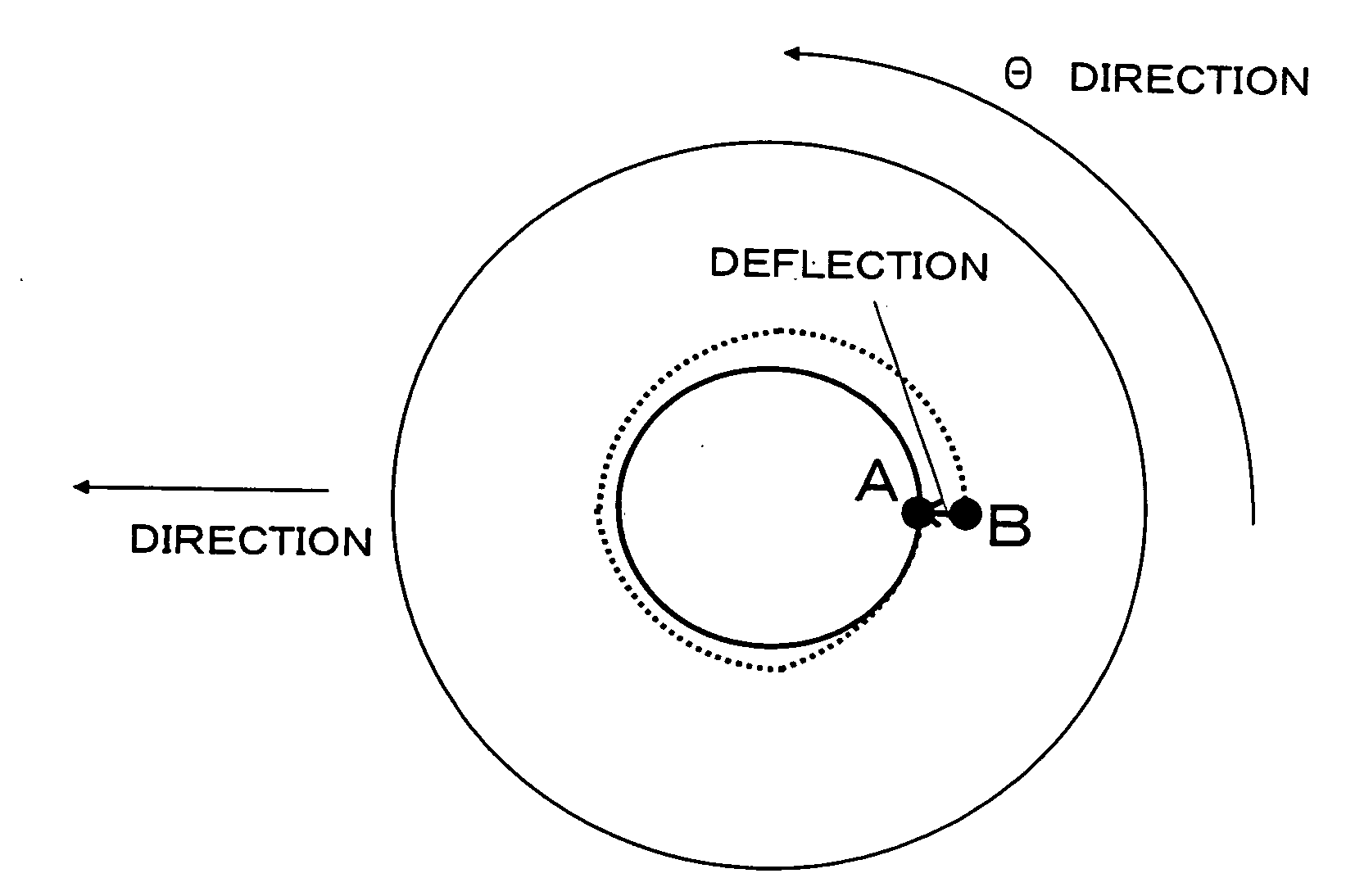
[0039] The electron beam irradiating method according to the embodiment is constituted so as to further perform exposure on a specific place which has been once exposed in the next exposing step and step(s) subsequent thereto, while changing a deflection intensity to an...

example 1

[0066] A manufacturing method of a magnetic recording medium according to an example 1 of the present invention will be explained with reference to FIGS. 3A and 4F.

[0067] An electron beam irradiating apparatus with acceleration voltage of 50 kV having an electron gun, a condenser lens, an objective lens, a blanking electrode, and an electron gun emitter of a ZO / W TFE (thermal field emission) type provided with a deflector which performs 20 nm deflection when applied with a voltage of 20 mV and performs 40 nm deflection when applied with a voltage of 40 mV was used.

[0068] On the other hand, after resist ZEP-520 produced by NIPPON ZEON CORP. was diluted to two times and the diluted resist was filtrated by a membrane filter with 0.2 μm mesh size, the filtrated resist was spin-coated on a 8-inch silicon wafer substrate 2 HMDS-processed, and the wafer substrate is pre-baked at a temperature of 200° C. for three minutes, so that a resist 4 with a film thickness of 0.1 μm was formed (see...

example 2

[0095] A manufacturing method of a magnetic recording medium according to an example 2 of the present invention will be explained. In the example 2, a magnetic recording medium was manufactured like the example 1 except for deflection intensity of an electron beam. Regarding the deflection intensity of an electron beam in this example, exposure was conducted in m (m denoted 1 to 120) sectors about (15k+8) (k denoted 0 or a natural number) round while increasing the deflection intensity in an address portion from 20×(m−1) / 120 [mV] to 20×(m−1) / 120+20×1 / 120×1000 / 10000 [mV] and increasing the deflection intensity in a track portion from 15+20×(m−1) / 120+20×1 / 120×1000 / 10000 [mV] to 15+20×m / 120 [mV].

[0096] A width of a groove of the track portion of a medium imprinted and processed was 100 nm, which was wider than that in the example 1.


PUM


Abstract

The present invention is to make it possible to form a fine pattern, and improve a recording density on a magnetic recording medium and increase signal intensity. There is provided an electron beam irradiating method which irradiates an electron beam on a resist to perform irradiating using an electron beam irradiating apparatus provided with a moving mechanism which moves a state on which a substrate applied with the resist is put in one horizontal direction, and a rotating mechanism which rotates the stage. The electron beam irradiating method includes: exposing a portion once exposed while changing a deflection amount of the electron beam at least one time in the next round and rounds subsequent thereto, when exposure is performed while a deflection amount of an electron beam is being gradually changed so as to draw a concentric circle for each round.

Description

CROSS-REFERENCE TO RELATED APPLICATION [0001] This application is based upon and claims the benefit of priority from prior Japanese Patent Application No. 2004-286420 filed on Sep. 30, 2004 in Japan, the entire contents of which are incorporated herein by reference. BACKGROUND OF THE INVENTION [0002] 1. Field of the Invention [0003] The present invention relates to an electron beam irradiating method and a manufacturing method of a magnetic recording medium. [0004] 2. Related Art [0005] In a technical trend to density growth in a hard disk, a medium structure of a so-called discrete type where a magnetic portion region generating magnetic signals has been defined by a non-magnetic portion has been proposed. Though a recording and reproducing system for a medium of a discrete type having data zones and servo zones has been described in JP-A-2004-110896 publication, the publication does not describe how to manufacture a medium of the discrete type. [0006] On the other hand, U.S. Pat. ...

Claims


Application Information

Patent Timeline
Patent Type & Authority Applications(United States)
IPC IPC(8): A61N5/00
CPCB82Y10/00B82Y40/00G03F7/2059G11B5/743G11B5/82G11B5/855H01J37/3174H01J2237/31766
Inventor OKINO, TAKESHIMORITA, SEIJIKAMATA, YOSHIYUKI
Owner KK TOSHIBA
Why Eureka
Try Eureka