Spread spectrum clock generating apparatus

a clock and spectrum technology, applied in the direction of generating/distributing signals, pulse techniques, instruments, etc., can solve the problems of increasing labor costs in optimizing design, causing transient response, and loss of stability of loops, etc., and achieve the effect of smooth spread spectrum clock

Active Publication Date: 2006-04-13
RENESAS ELECTRONICS CORP
View PDF3 Cites 19 Cited by
  • Summary
  • Abstract
  • Description
  • Claims
  • Application Information

AI Technical Summary

Benefits of technology

[0023] Further, in accordance with the present invention, a step phase error in the clock output prevailing when an up signal or down signal is input to the phase interpolator is decided by the resolution of the phase interpolator. As a result, a smooth spread spectrum clock can be generated.
[0024] Furthermore, in accordance with the present invention, the arrangement is such that the control circuit is caused to operate by a frequency-divided clock obtained by frequency-dividing the input clock. As a result, it is possible to apply frequency modulation to clocks of higher frequencies.
[0025] Furthermore, in accordance with the present invention, it is possible to achieve a smooth transition between absence and presence of a spread spectrum clock function.

Problems solved by technology

Since the PLL is in the negative feedback loop, a transient response is caused by the entered step phase error.
If the damping factor is small, on the other hand, there is a possibility that the stability of the loop will be lost.
Furthermore, since the characteristic of a spread spectrum clock generator is decided by control of the pulse-swallow frequency divider and the overall characteristic of transient response due to step phase error, a large number of design parameters exist and labor expended in optimizing design increases.
As a consequence, control is complicated and it is necessary to finely adjust the amount of delay of the delay circuits.
However, it is difficult to achieve a smooth, seamless transition owing to the fine adjustment of amount of delay and the use of m or more clock generators.
Further, if it is attempted to finely adjust phase resolution by increasing the number of clock generators for m different phases, the oscillating frequency of the ring oscillator will decline and the required frequency will no longer be obtained.
These functions are not incorporated in conventional spread spectrum clock generators and therefore a transient change in frequency occurs at the time of changeover and communication may be interrupted.
A system set forth in Patent Document 3 cited above has a function for controlling a spread spectrum clock but a problem with this system is that the clock frequency fluctuates sharply owing to this control.

Method used


Image

  • Spread spectrum clock generating apparatus
  • Spread spectrum clock generating apparatus
  • Spread spectrum clock generating apparatus

Examples


Embodiment Construction

[0039] Preferred embodiments of the present invention will be described in detail with reference to the drawings. The principle of a referential example of the invention will be described first, followed by a description of the preferred embodiments.

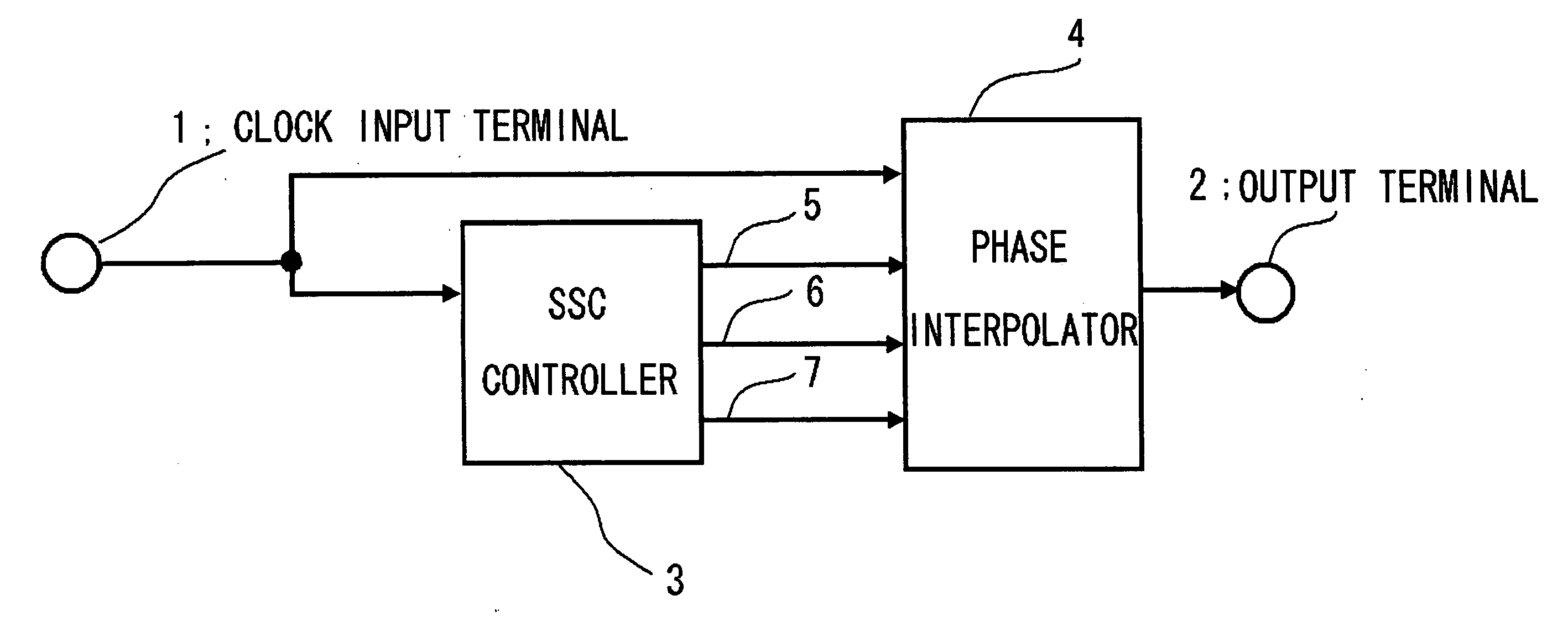
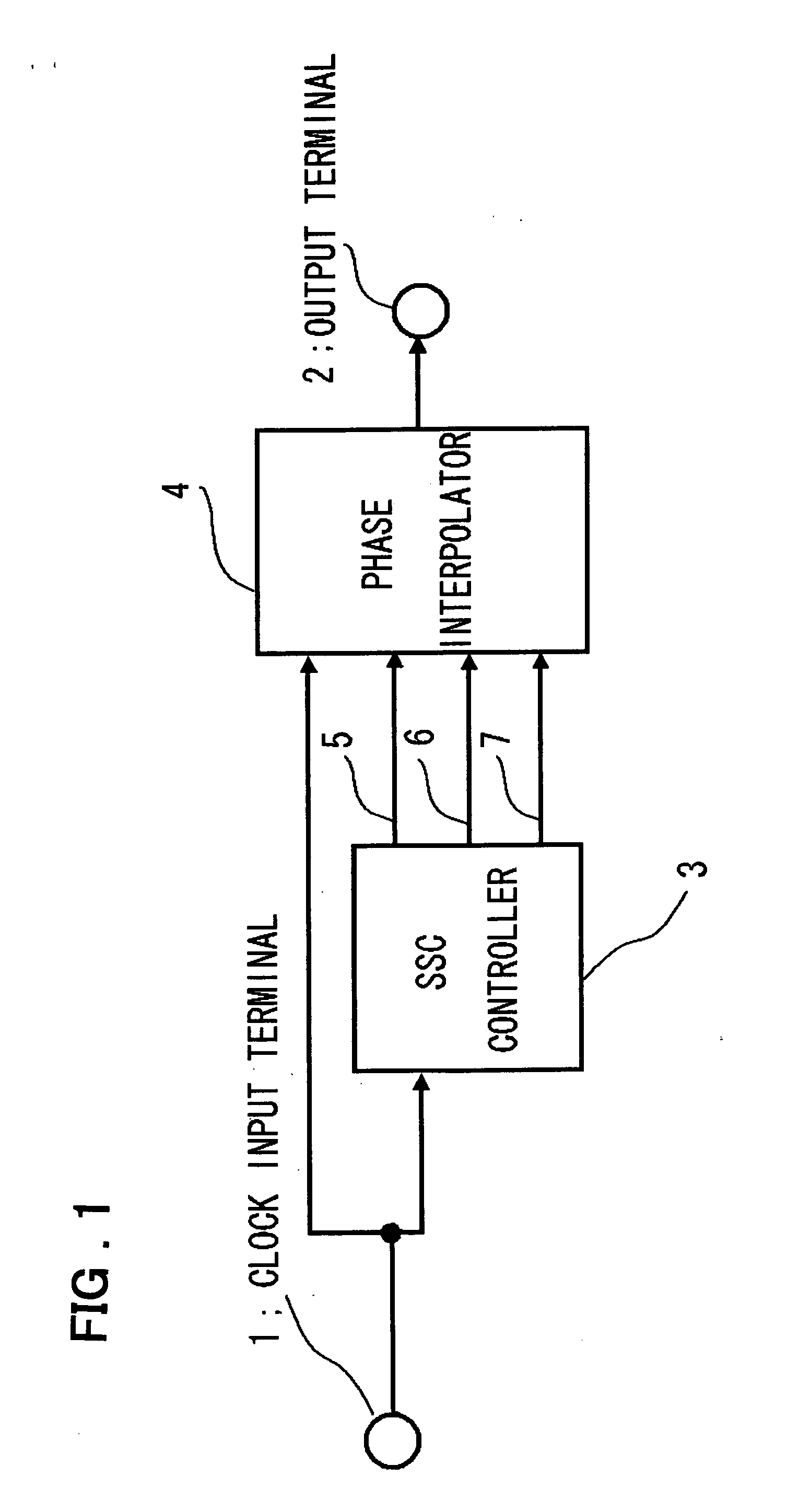
[0040]FIG. 1 is a block diagram illustrating the configuration of a first referential example of the present invention. As illustrated in FIG. 1, the referential example includes a phase interpolator 4 and a controller 3 (referred to also as an “SSC controller”). A clock signal that enters from an input terminal 1 is input to both the controller 3 and phase interpolator 4.

[0041] The controller 3 outputs a timing signal 5 that is generated based upon the input clock signal. Further, the controller 3 counts the input clock signal and, on the basis of the count, performs control to output an up signal 6, which instructs the phase interpolator 4 to advance the phase of the output clock signal thereof a prescribed amount, and / or a down sign...


PUM


Abstract

Disclosed is a spread spectrum clock generator comprising a phase interpolator, which receives a clock signal from a clock input terminal and a control signal (an up signal and/or down signal), for adjusting the phase of an output clock signal in accordance with said control signal and outputting the resultant clock signal, and a control circuit receiving and counting the clock signal that enters from the clock input terminal and outputting said control signal (up signal or down signal), which is for varying the phase of the output clock signal based upon the result of the count, to the phase interpolator. The phase of the output clock signal from the phase interpolator varies with time and the output clock signal is frequency-modulated within a prescribed frequency range. A changeover between absence and presence of a spread spectrum clock function is performed, without a sudden fluctuation in frequency, in accordance with a frequency-modulation start signal and frequency-modulation stop signal that enters from an SSC control terminal.

Description

FIELD OF THE INVENTION [0001] This invention relates to a clock generating circuit and, more particularly, to a spread spectrum clock generator. BACKGROUND OF THE INVENTION [0002] When a clock generator in an electronic device generates a single frequency, emission increases at this frequency and higher harmonics. For this reason, use is made of a spread spectrum clock generator that reduces the peak of unnecessary emissions by frequency modulation and diminishes EMI (electromagnetic interference). [0003] A PLL (phase-locked loop) in which a pulse-swallow frequency divider is provided in a feedback counter generally is used as a conventional spread spectrum clock generator of this kind (e.g., see Non-patent Document 1 below). This PLL implements frequency modulation by affording two integers A and A-1 as divider ratios and switching between A and A-1. By changing the proportions of A and A-1 at predetermined fixed intervals, average frequency f is varied to thereby generate a spread...

Claims


Application Information

Patent Timeline
Patent Type & Authority Applications(United States)
IPC IPC(8): G06F1/04H04B1/69H04L7/00H04B1/707
CPCH03K3/0322H03K3/84H03K5/133H03K2005/00052H03K2005/00247H04B15/04H04B2215/064H04B2215/067
Inventor OGASAWARA, KAZUO
Owner RENESAS ELECTRONICS CORP
Why Eureka
Try Eureka