Filter having parasitic inductance cancellation

a filter and parasitic inductance technology, applied in the field of filters and components for suppressing electrical signals, can solve the problems of reducing the performance of such filters, limiting the ability to shunt ripple at high frequencies, adding considerable size, complexity, and cost to filters, and achieves the effect of improving performance over frequency

Inactive Publication Date: 2006-04-13
MASSACHUSETTS INST OF TECH
View PDF0 Cites 6 Cited by
  • Summary
  • Abstract
  • Description
  • Claims
  • Application Information

AI Technical Summary

Benefits of technology

[0009] The present invention provides an electrical component that cancels the effect of the series inductance of a capacitive element or other element or circuit. With this arrangement, a low-pass filter including an electrical component in the shunt path with inductance cancellation provides enhanced performance over frequency by maintaining a relatively low shunt path impedance out to relatively high frequencies.
[0012] In another aspect of the invention, a filter includes a component having a capacitive element and capacitive-path inductance cancellation provided by coupled windings. The coupled windings cancel the equivalent series inductance of the capacitor so as to enhance the filter performance over frequency.

Problems solved by technology

However, the performance of such filters can be degraded by the filter capacitor parasitics.
For example, a typical aluminum electrolytic capacitor may appear inductive (impedance rising with frequency) at frequencies above 50-100 kHz, thereby limiting its ability to shunt ripple at high frequencies.
While these approaches can reduce parasitic effects to some extent, they can add considerable size, complexity, and cost to the filter.

Method used


Image

  • Filter having parasitic inductance cancellation
  • Filter having parasitic inductance cancellation
  • Filter having parasitic inductance cancellation

Examples


examples

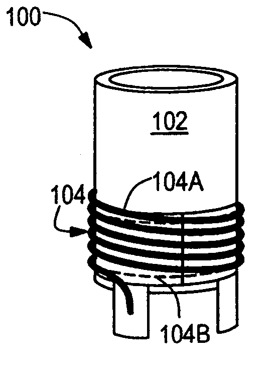
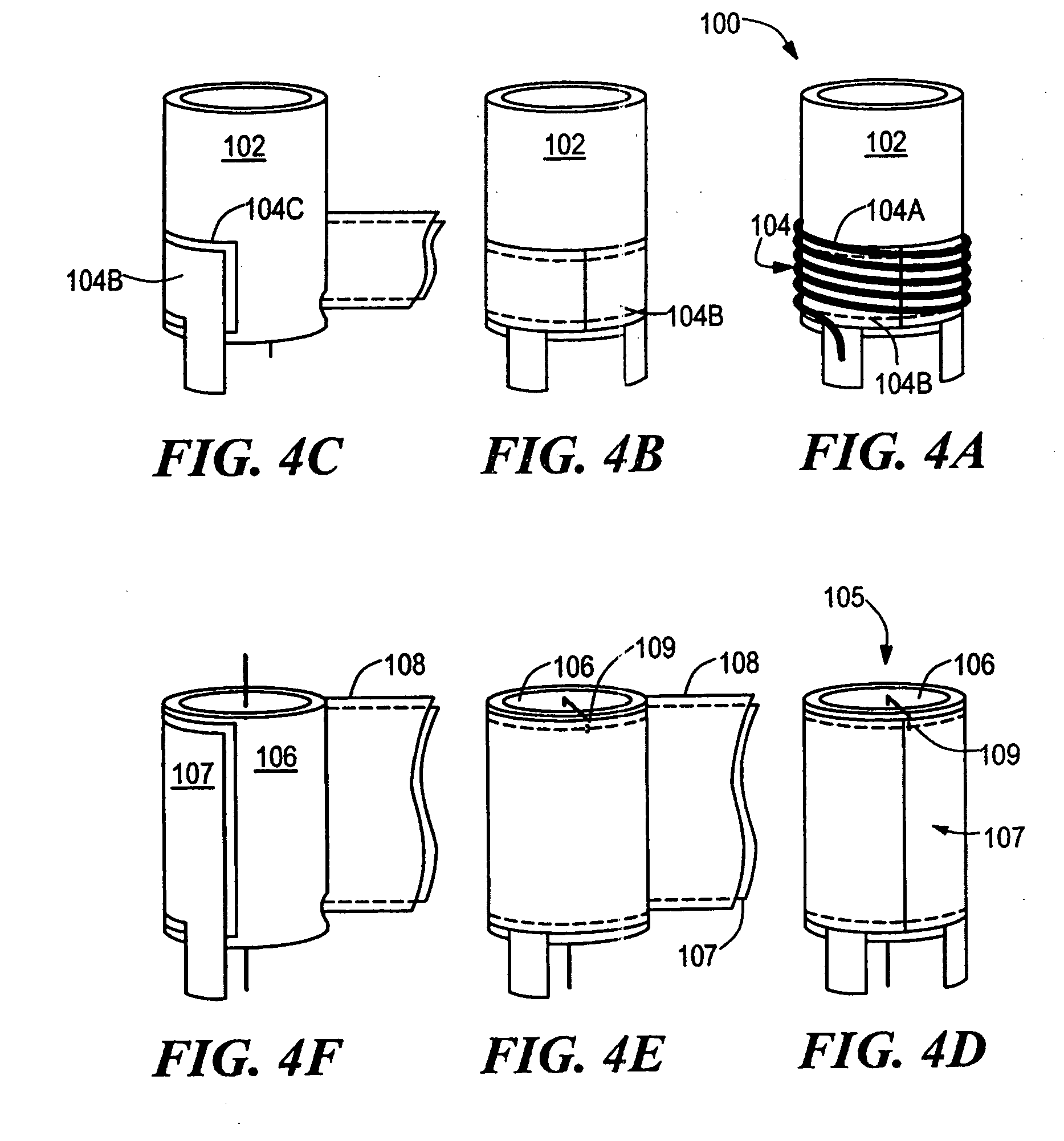
[0093] FIGS. 15A-C show various fabrication stages of an illustrative prototype filter element 700 having inductance cancellation in accordance with the present invention. Inductance cancellation magnetics 702a,b were wound on the outside of a United Chemi-Con U767D 2200 μF, 35 V electrolytic capacitor 704. A first (capacitor-path) winding 702a, which is shown as a foil winding, is added about the capacitor package. A second (inductive-path) winding 702b, which is shown as a wire winding, is placed over the first winding 702a. Use of the capacitor body as the winding form minimizes the overall volume of the filter element and illustrates the possibility of incorporating the coupled windings inside the capacitor package.

[0094] The capacitor-path winding 702a is wound with 1 inch wide, 1 mil thick copper tape, insulated with 1 mil mylar tape. One and three fourths turns on the capacitor body (circumference of 7.1 cm) were found to be sufficient to achieve a desired level of coupling....


PUM


Abstract

An electrical component includes a capacitive impedance and a shunt path inductance cancellation feature provided by coupled windings. A filter having a capacitor with capacitor-path inductance cancellation provides enhanced performance over frequency compared with conventional capacitors.

Description

CROSS REFERENCE TO RELATED APPLICATIONS [0001] The present application is a continuation-in-part of U.S. patent application Ser. No. 10 / 082,616, filed on Feb. 25, 2002, which is incorporated herein by reference.STATEMENT REGARDING FEDERALLY SPONSORED RESEARCH [0002] The Government may have certain rights in the invention pursuant to Contract No. N000140010381 sponsored by the U.S. Office of Naval Research.FIELD OF THE INVENTION [0003] The present invention relates generally to electrical components and filters and, more particularly, to components and filters for suppressing electrical signals. BACKGROUND OF THE INVENTION [0004] As is well known in the art, electrical and electronic applications can utilize electrical filters to suppress undesirable signals, such as electrical noise and ripple. Such filters are designed to prevent the propagation of unwanted frequency components from the filter input port to the filter output port, while passing desirable components. Low-pass filter...

Claims


Application Information

Patent Timeline
Patent Type & Authority Applications(United States)
IPC IPC(8): H03H7/01
CPCH03H7/0115H03H7/1708H03H7/1766H03H2001/0078H03H7/09H03H2001/0042H03H2001/005H03H2001/0085
Inventor PERREAULT, DAVID J.NEUGEBAUER, TIMOTHY C.PHINNEY, JOSHUA W.
Owner MASSACHUSETTS INST OF TECH
Why Eureka
Try Eureka