Ribbon-microphone transducer

a microphone and microphone technology, applied in the field of microphones, can solve the problems of large disadvantage, large disadvantage, and inability to adjust the frequency response, and achieve the effect of reducing the overall effective front-to-back distan

Inactive Publication Date: 2006-04-13
BULLDOG AUDIO
View PDF3 Cites 29 Cited by
  • Summary
  • Abstract
  • Description
  • Claims
  • Application Information

AI Technical Summary

Benefits of technology

[0014] By angling the magnetic poles (and/or the corresponding magnets) in the foregoing manner, a transducer according to the present invention often can simultaneously achieve a number of different design goals. These include: reducing the overall effective front-to-rear distance around the ribbon, specifically reducing the front-to-rear distance around the ribbon near the center of its length, providing adequate magnetic flux along the entire length of the ribbon (even in embodiments where the front-to-rear distance is minimized along segments of the ribbon's length), and providing the magnetic flux at an approximately right angle to the ribbon.
[0015] In more particular aspects, the transducer of the present invention includes various combinations of the following features: at least two magnetic poles are provided adjacent each side of the ribbon, the magnetic poles are oriented in a cross configuration, two adjacent magnets on each side of the ribbon are separated by a gap (e.g., of at least 0.10 inch in length), each of the magnetic poles is provided by a disti

Problems solved by technology

In a way, this made up for generational losses in analog tape mediums, as well as deficiencies in radio and TV broadcasting systems.
This same characteristic (actually a form of distortion) would prove to be a great disadvantage with the new digital technology that was to come.
However, the small size and durability of condenser microphones furthered

Method used


Image

  • Ribbon-microphone transducer
  • Ribbon-microphone transducer
  • Ribbon-microphone transducer

Examples


Embodiment Construction

)

[0025] The present disclosure covers inventions that are claimed herein and in the commonly assigned patent application filed concurrently herewith, titled “Ribbon Microphone Incorporating a Special-Purpose Transformer and / or Other Transducer-Output Circuitry”, which application is incorporated by reference herein as though set forth herein in full.

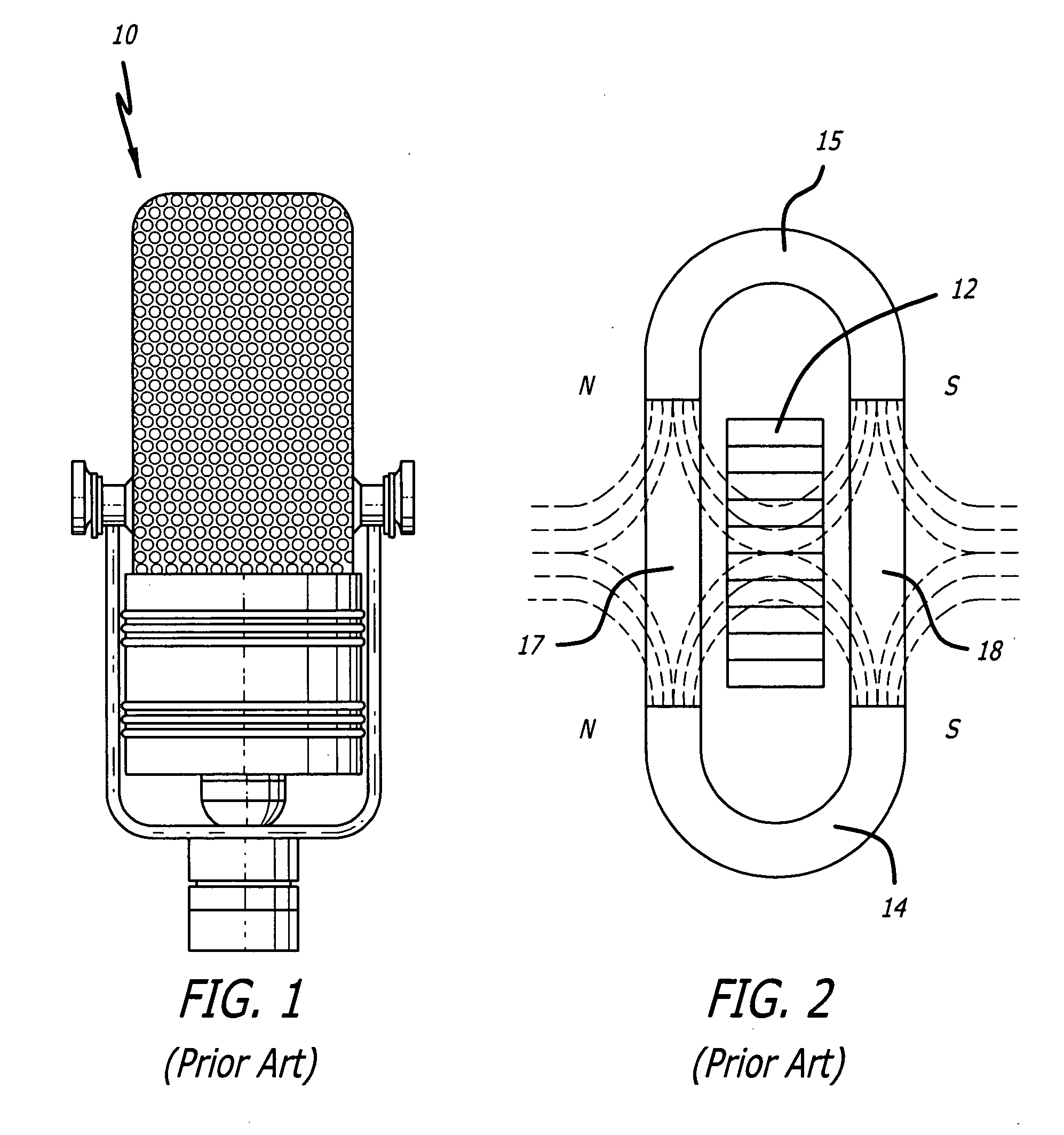
[0026] The generating element of a conventional ribbon microphone produces a substantially weaker signal than that produced by a modern condenser microphone, and this signal often is considered inadequate to drive present-day preamplifiers, many of which having been designed for the higher output condenser microphones. Another issue is that conventional “passive” (unpowered) ribbon microphones are very sensitive to loading and require preamplifier input stages that possess higher input impedances than those of most contemporary preamplifier designs.

[0027] Loading occurs when the input impedance of the preamplifier is lower than what th...


PUM


Abstract

Provided is a ribbon-microphone transducer that uses an angled-magnet structure and/or a gap (e.g., near the center of the ribbon) in the magnetic structure in order to provide improved sensitivity and frequency response.

Description

BACKGROUND OF THE INVENTION [0001] 1. Field of the Invention [0002] The present invention pertains to the improvement of a particular type of microphone, called a ribbon microphone, and specifically is applicable to improved designs for the transducer of a ribbon microphone. [0003] 2. Description of the Related Art [0004]FIG. 1 illustrates a common conventional ribbon microphone 10. Such a microphone typically would be approximately 8 inches high, 4 inches wide and 3 inches deep, and would weigh approximately 7.5 pounds. [0005] The transducer for ribbon microphone 10 is shown in FIG. 2. In its simplest form, a ribbon microphone, such as microphone 10, uses a ribbon 12 (e.g., a very thin piece of corrugated aluminum foil) suspended in a magnetic field. When the ribbon 12 is caused to vibrate by an acoustic (or sound) pressure wave, a voltage is induced along the length of ribbon 12 that ideally is proportional to the frequency and intensity of the sound wave striking it. The use of o...

Claims


Application Information

Patent Timeline
IPC IPC(8): H04R25/00
CPCH04R9/08H04R9/048
Inventor ROYER, DAVID E.PERROTTA, RICHARD T.
Owner BULLDOG AUDIO
Why Eureka
Try Eureka