Bearing device and supporting shaft for bearing device

a technology of bearing device and supporting shaft, which is applied in the direction of bearing unit rigid support, mechanical equipment, machines/engines, etc., can solve the problems of increasing costs, and achieve the effects of high hardness, excellent abrasion resistance, and high hardness

Inactive Publication Date: 2006-04-13
JTEKT CORP
View PDF1 Cites 6 Cited by
  • Summary
  • Abstract
  • Description
  • Claims
  • Application Information

AI Technical Summary

Benefits of technology

[0027] According to the supporting shaft for the bearing device of the present invention, in consideration of attachment of an extraneous material or abrasion of the shaft main body of the supporting shaft, a construction having a high hardness and excellent abrasion resistance can be obtained by a high-concentration carburizing process or a nitrifying process. In this case, although the shaft end of the shaft main body has a high hardness, a cap having a low hardness may be fitted to the both shaft ends and caulked to the inner-diameter side edge of the shaft-end insertion hole, thereby preventing the supporting shaft from escaping from the shaft-end insertion hole of the shaft main body. As the result, although the entire shaft main body has a high hardness and extremely excellent abrasion resistance by a high-concentration carburizing process, the limit of the anti-carburizing process for the both shaft ends of the shaft main body is reduced and a low-cost heating process such as a complete quenching can be used, thereby significantly reducing the cost. Furthermore, since the both shaft ends of the shaft main body need not be press-fitted to the shaft-end insertion holes after the complete quenching, the both shaft ends are not broken or cracked by the press fitting, and, since the small-diameter shaft end of the shaft main body need not be annealed after the complete quenching, the cost is reduced. In addition, since the cap has the same outer diameter as that of the middle portion of the shaft main body, the entire outer diameter of the supporting shaft is constant. Accordingly, the supporting shaft is apt to be inserted into the shaft end insertion hole of one opposed sidewall and the shaft end insertion hole of the other opposed sidewall from the outside of one of the opposed sidewalls and thus the assembling of the bearing device is easy.
[0028] According to the present invention, it is possible to provide a bearing device in which a shaft main body of a supporting shaft has a high hardness and excellent abrasion resistance or improved life span by a low-cost heating process, and the ends of the shaft main body are caulked to the inner-diameter side edges of insertion holes to be prevented from escaping from the insertion holes while ensuring a mechanical strength.

Problems solved by technology

Furthermore, instead of the anti-carburizing process, when the middle portion of the supporting shaft 22 is partially quenched (RF-quenched), a cost increases.

Method used


Image

  • Bearing device and supporting shaft for bearing device
  • Bearing device and supporting shaft for bearing device
  • Bearing device and supporting shaft for bearing device

Examples


first embodiment

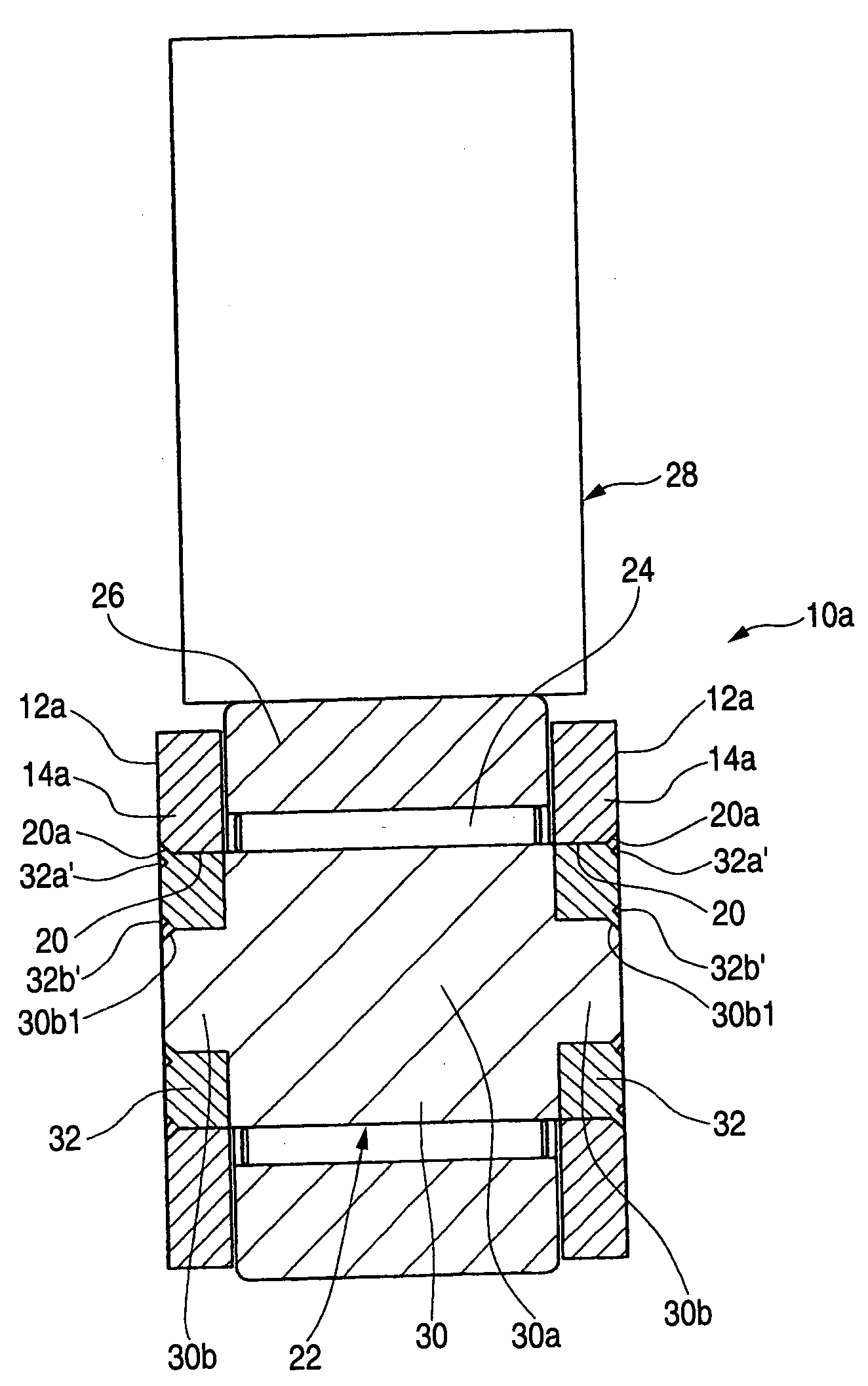
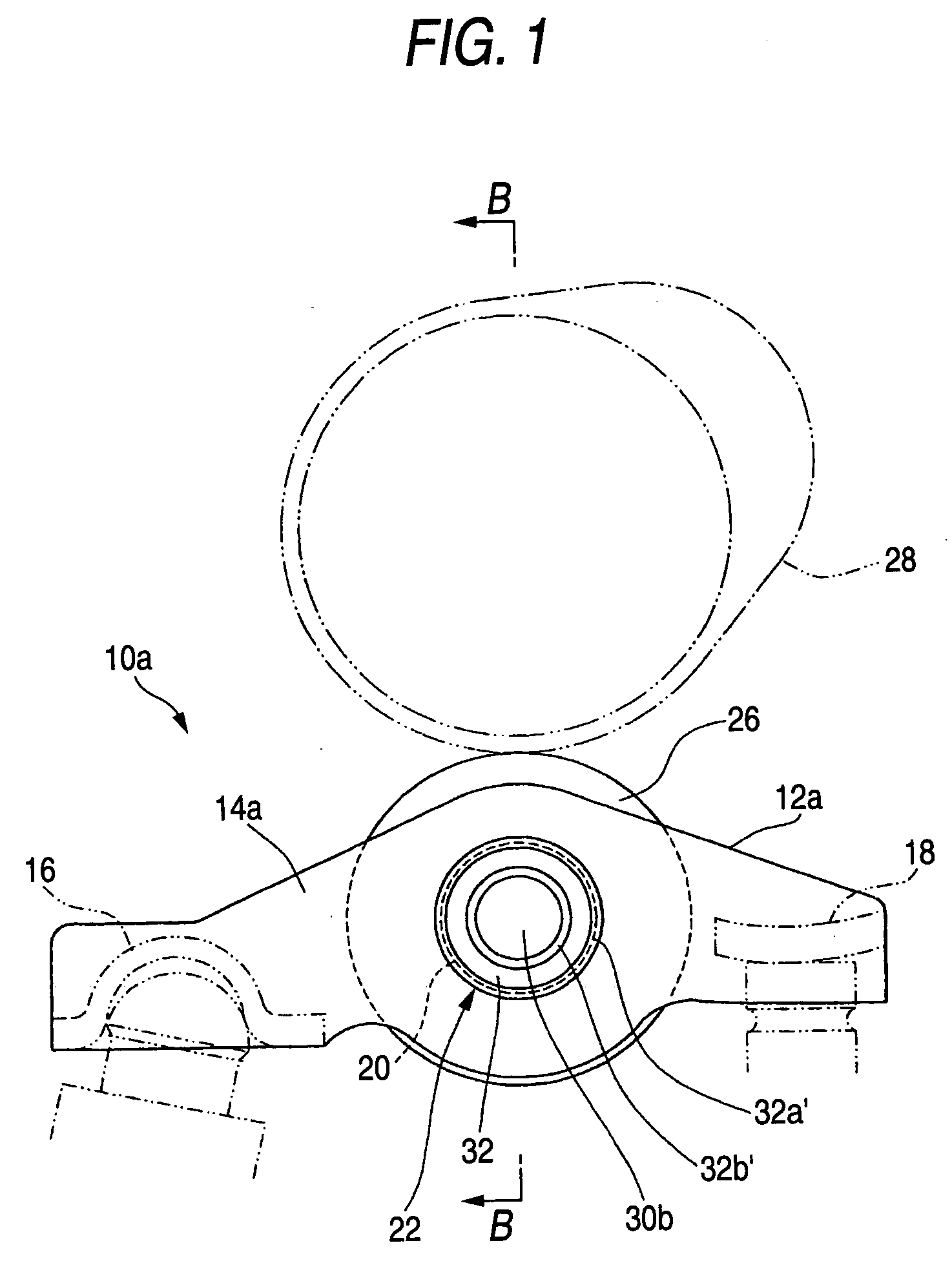
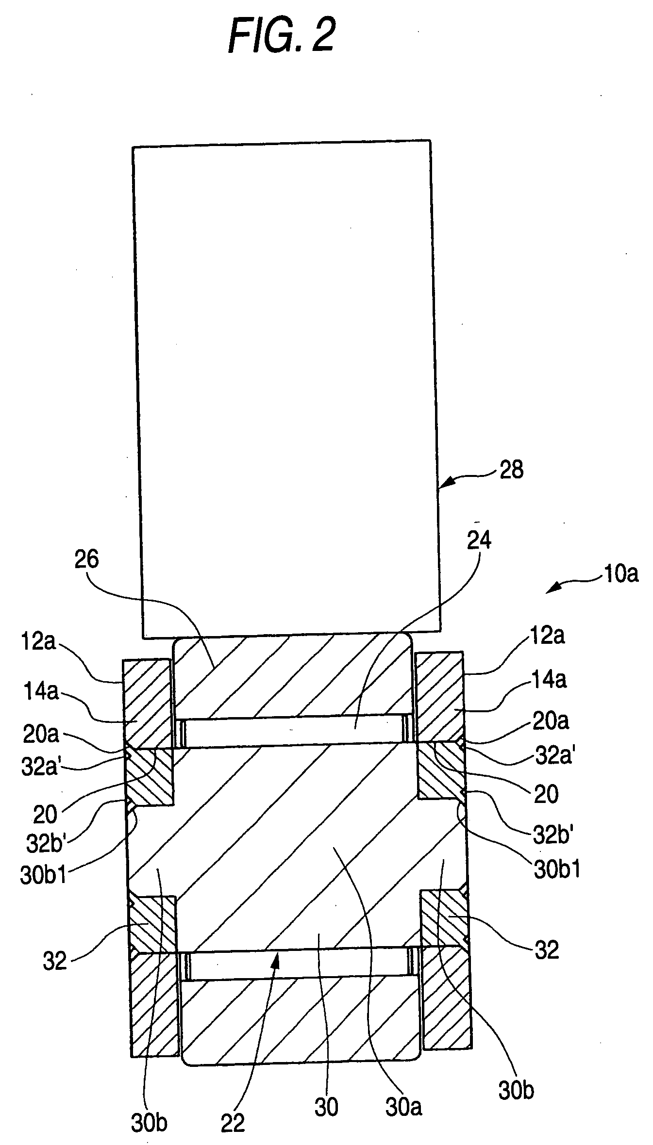
[0039] Hereinafter, a rocker arm for a valve operating mechanism of an internal combustion engine according to a first embodiment of the invention will be described with reference to the accompanying drawings. FIGS. 3 through 7 illustrate a bearing device and a supporting shaft for the bearing device according to the present invention, and FIGS. 1 and 2 illustrate a rocker arm according to the embodiment of the present invention. FIG. 1 is a side view of a rocker arm, FIG. 2 is a cross-sectional view taken along line B-B of the rocker arm of FIG. 1, FIG. 3 is a side view of a bearing device according to the present invention, FIG. 4 is a side view of a shaft main body of a supporting shaft in FIG. 3, FIG. 5 is a cross-sectional side view of a cap of the supporting shaft in FIG. 3, FIG. 6 is a cross-sectional view of the supporting shaft in a state that the cap is fitted to the both shaft ends of the shaft main body, and FIG. 7 is a perspective view of the supporting shaft.

[0040] Re...

second embodiment

[0047] A construction applied to a gear supporting shaft 51 of a planet gear device 50 according to a second embodiment of the present invention is shown in FIG. 8.

[0048] By caulking and fixing the ends of caps 54 which are inserted into small-diameter shaft ends 53 of a shaft main body 52 to carriers of opposed sidewalls 55, the same effect as the first embodiment can be obtained.

[0049] In FIG. 10, 56 denotes a planet gear, 57 denotes a sun gear, 58 denotes an inner gear, 59 denotes a first rotary shaft, 60 denotes a second rotary shaft, 61 denotes a caulking portion of the cap 53 for the opposed sidewall 55, and 62 denotes a caulking portion of the cap 54 for the shaft main body 52.


PUM


Abstract

The bearing devices includes a pair of opposed sidewalls, a supporting shaft which is inserted into shaft end insertion holes provided in the both opposed sidewalls, and a roller supported between the both opposed sidewalls by the supporting shaft. The supporting shaft includes a shaft main body that is made of a steel product subjected to a heating process and has a step shape in which the outer diameters of the both shaft ends are smaller than that of a middle portion and caps which is fitted to the both shaft ends and of which the end can be caulked. An end outer-diameter side edge of the cap is caulked to an inner-diameter side edge of the insertion hole.

Description

BACKGROUND OF THE INVENTION [0001] The present invention relates to a bearing device and a supporting shaft for the bearing device, and more particularly, to a rocker arm which is installed in a valve operating mechanism of an engine of a vehicle to open or close a valve, a supporting shaft for the rocker arm, a planet gear device for forming an automatic transmission (AT) of a vehicle, and a supporting shaft for the gear. Specially, the present invention relates to a rocker arm in which both ends of a supporting shaft including at the middle portion a raceway surface around which a roller rolls are inserted into shaft-end insertion holes of a pair of opposed sidewalls, a supporting shaft for the rocker arm, a planet gear device, and a supporting shaft for the gear device. [0002] A rocker arm is installed in a valve operating mechanism of an engine of a vehicle and switches a valve of the engine of the vehicle by rotating its body around a lash adjuster receiver (pivot receiver) in ...

Claims


Application Information

Patent Timeline
Patent Type & Authority Applications(United States)
IPC IPC(8): F16C13/00
CPCF01L1/146F01L1/18F01L2105/02F16C13/006F16H53/06F16C2360/18F01L2305/02
Inventor OCHI, SHINYANISHIUCHI, JUNNISHIZAWA, CHIAKIWASEDA, YOSHITAKA
Owner JTEKT CORP
Why Eureka
Try Eureka