Apparatus and method for a nanocalorimeter for detecting chemical reactions

a nanocalorimeter and chemical reaction technology, applied in the field of system and method of an improved nanocalorimeter, can solve the problems of inability inability to use standard calorimeters effectively to monitor a large number of reactions, and inability to measure very small samples

Inactive Publication Date: 2006-04-13
PALO ALTO RES CENT INC
View PDF39 Cites 35 Cited by
  • Summary
  • Abstract
  • Description
  • Claims
  • Application Information

AI Technical Summary

Benefits of technology

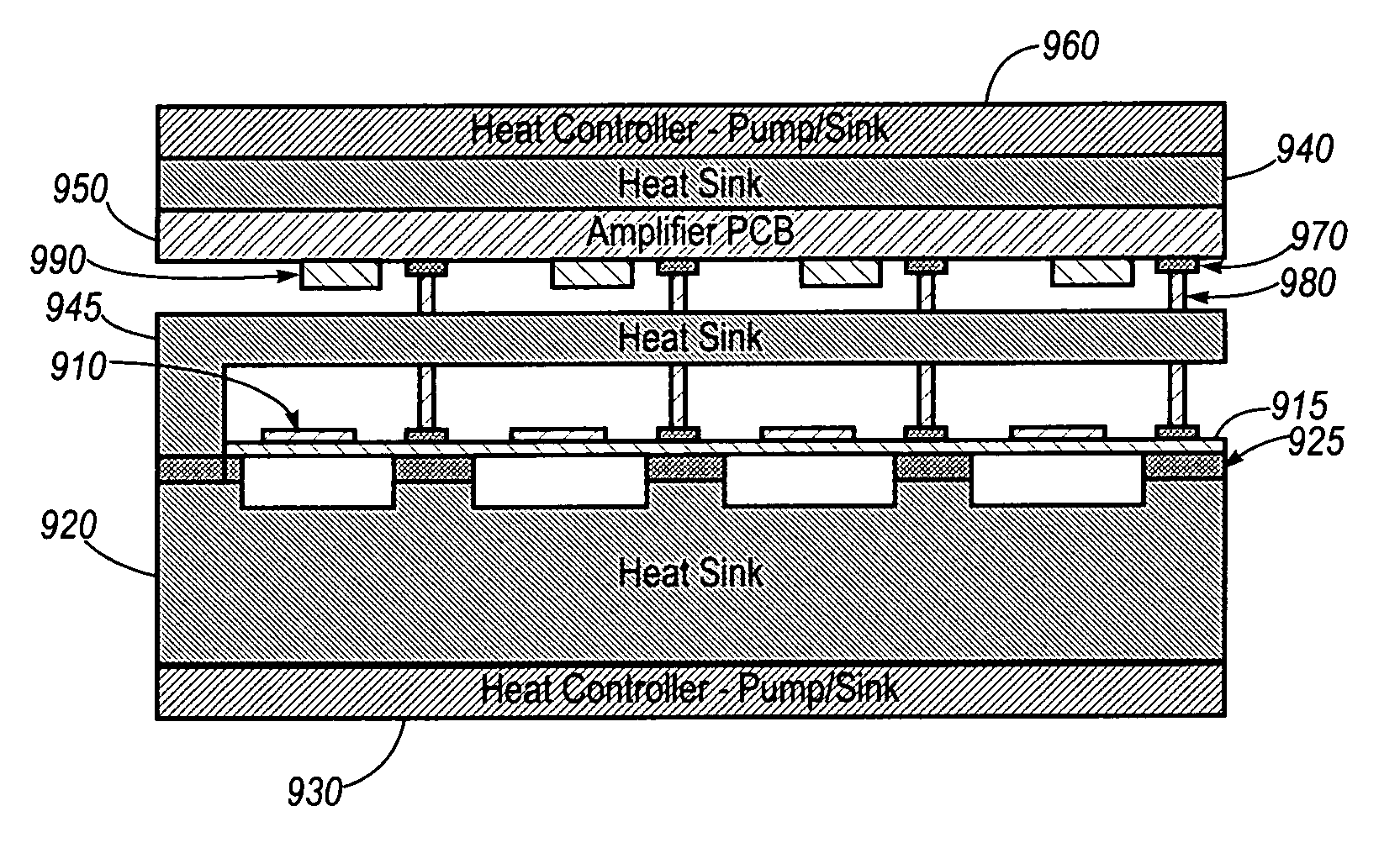
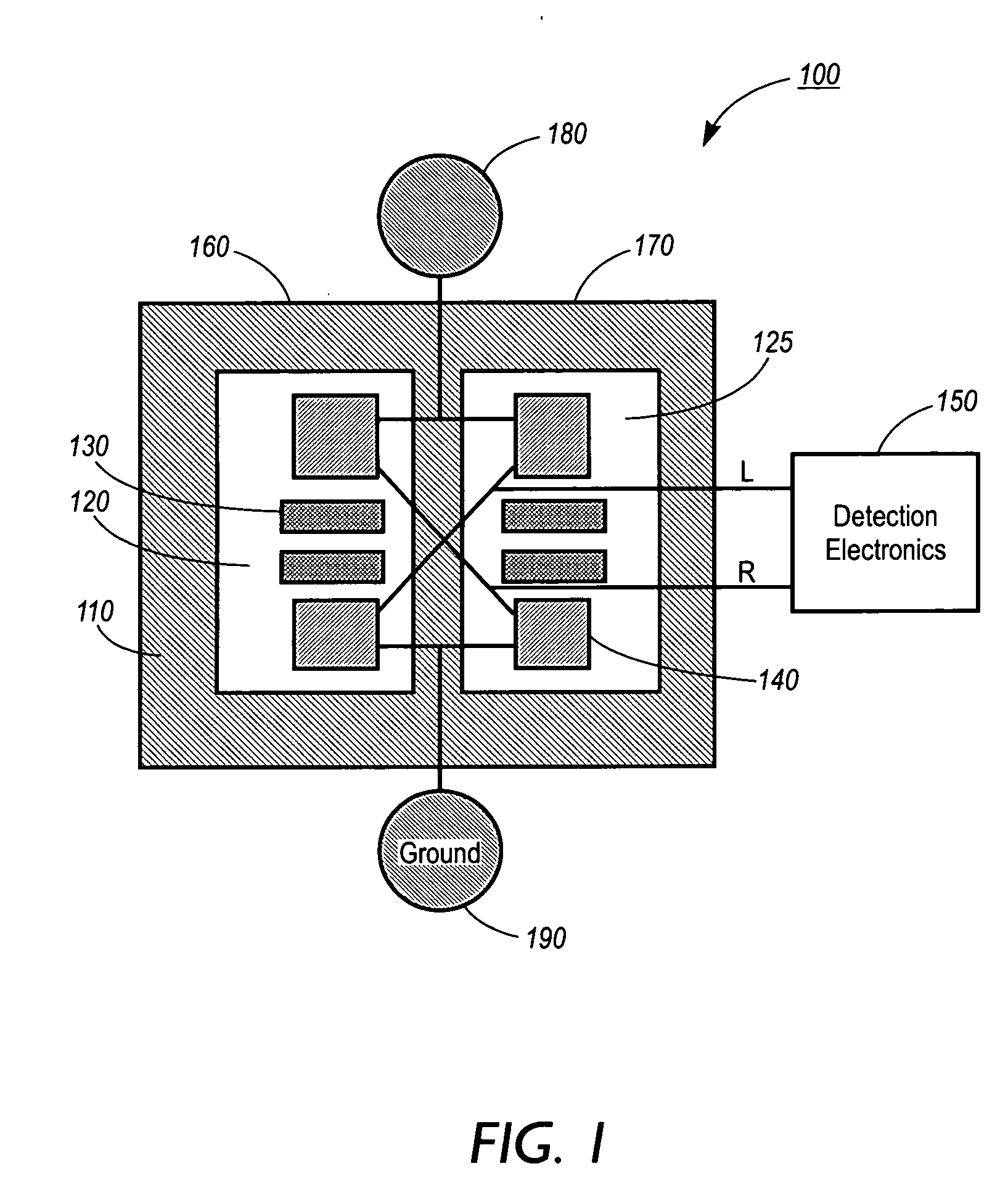
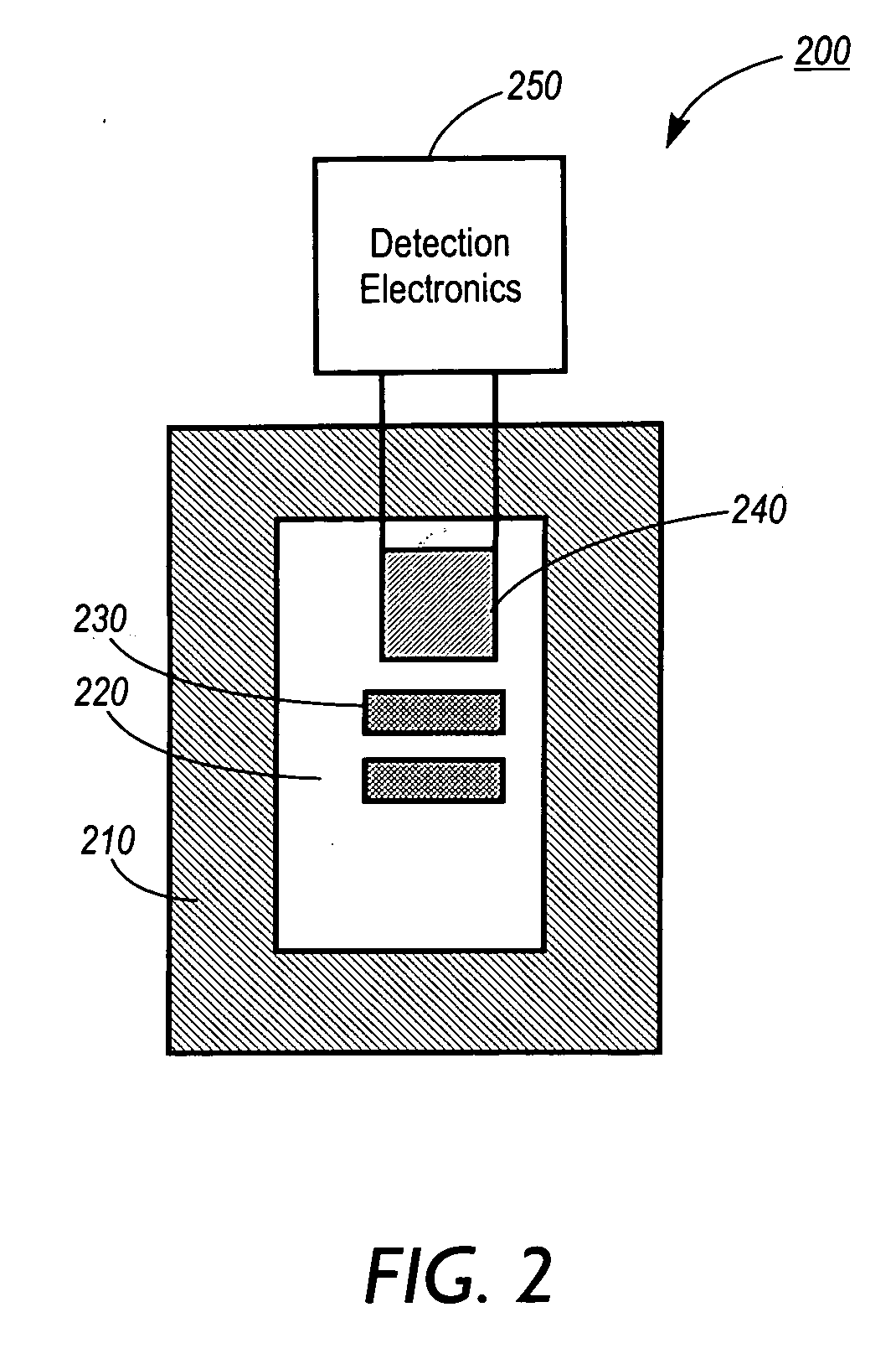
[0019] The disclosed embodiments provide examples of improved solutions to the problems noted in the above Background discussion and the art cited therein. There is shown in these examples an improved method for detecting chemical reactions uses a nanocalorimeter having a substrate including thermal isolation capability residing on the substrate, thermal equilibration regions residing within the thermal isolation capability, and thermal measurement capability residing within each of the thermal equilibration regions. The thermal measurement device is connected to detection electronics. The method includes depositing drops of potentially reactive chemical solutions within the thermal equilibration region. These potentially reactive solution drops are merged through the use of drop merging electrodes residing within the thermal isolation region. The thermal change occurring within the merged solution drops is then measured with the detection electronics.

Problems solved by technology

As such, these systems cannot be used to measure very small samples, as might be desired for precious or highly reactive materials.
Furthermore, standard calorimeters cannot be used effectively to monitor a large number of reactions of small sample size in parallel, as is required in order to perform studies using combinatorial chemistry techniques.
In some cases, the sample to be studied is precious, and it might not be acceptable to use the relatively large amount of material required by a standard microcalorimeter to perform only one measurement.
However, the inhibitor assay requires time and expense to develop the assay.
Attaching the fluorescent marker can often take 3 months of development or more and cost $250 k or more once the marker ligand is identified.

Method used


Image

  • Apparatus and method for a nanocalorimeter for detecting chemical reactions
  • Apparatus and method for a nanocalorimeter for detecting chemical reactions
  • Apparatus and method for a nanocalorimeter for detecting chemical reactions

Examples


Embodiment Construction

[0032] As used herein, the term “ligand” refers to an agent that binds a target molecule. In the case in which the target molecule is a target protein, the agent may bind the target protein when the target protein is in its native conformation, or when it is partially or totally unfolded or denatured. According to the present invention, a ligand is not limited to an agent that binds a recognized functional region of the target protein e.g. the active site of an enzyme, the antigen-combining site of an antibody, the hormone-binding site of a receptor, a cofactor-binding site, and the like. In practicing the present invention, a ligand can also be an agent that binds any surface or internal sequences or conformational domains of the target protein. Therefore, the ligands of the present invention encompass agents that in and of themselves may have no apparent biological function, beyond their ability to bind to the target protein in the manner described above.

[0033] As used herein, th...


PUM

PropertyMeasurementUnit
volumesaaaaaaaaaa
thicknessaaaaaaaaaa
thicknessaaaaaaaaaa

Abstract

A method for detecting chemical reactions uses a nanocalorimeter having a substrate including thermal isolation capability residing on the substrate, thermal equilibration regions residing within the thermal isolation capability, and thermal measurement capability residing within each of the thermal equilibration regions. The thermal measurement device is connected to detection electronics. The method includes depositing drops of potentially reactive chemical solutions within the thermal equilibration region. These potentially reactive solution drops are merged through the use of drop merging electrodes residing within the thermal isolation region. The thermal change occurring within the merged solution drops is then measured with the detection electronics.

Description

CROSS REFERENCE TO RELATED APPLICATIONS [0001] This is a divisional of U.S. application Ser. No. 10 / 114,611 filed Apr. 1, 2002 by the same inventors, and claims priority therefrom. This divisional application is being filed in response to a restriction requirement in that prior application and contains re-written and / or additional claims to the restricted subject matter. [0002] The following application, Attorney Docket Number D / A1578Q, U.S. application Ser. No. 10 / 115,336, filed Mar. 29, 2002, titled “Apparatus and Method for Using Electrostatic Force to Cause Fluid Movement”, is assigned to the same assignee of the present application. The entire disclosure of this application is totally incorporated herein by reference in its entirety. INCORPORATION BY REFERENCE [0003] The following U.S. patents are fully incorporated herein by reference: U.S. Pat. No. 5,967,659 (“Ultrasensitive Differential Microcalorimeter with User-selected Gain Setting” to Plotnikov et al.); U.S. Pat. No. 6,0...

Claims


Application Information

Patent Timeline
Patent Type & Authority Applications(United States)
IPC IPC(8): G01K17/02G01N25/20G01N25/48
CPCB82Y15/00G01N25/4846G01N25/4866Y10T436/2575Y10T436/25Y10T436/25625Y10S977/957
Inventor BELL, ALAN G.BRUCE, RICHARD H.ELROD, SCOTT A.PEETERS, ERICTORRES, FRANCISCO E.
Owner PALO ALTO RES CENT INC
Why Eureka
Try Eureka