Watercraft

a technology for watercraft and stern, applied in waterborne vessels, vessel parts, marine propulsion, etc., can solve the problems of large space requirement within the stern region for the raised underwater transmission and propeller, the tilting of the outboard motor, and it is almost impossible for the person steering the watercraft to continuously monitor the water surface and underwater topography

Inactive Publication Date: 2006-04-13
SUPRAVENTURES
View PDF13 Cites 16 Cited by
  • Summary
  • Abstract
  • Description
  • Claims
  • Application Information

AI Technical Summary

Benefits of technology

[0015] In the case of outboard systems, the pivot mechanism may be at the level of the motor—with the advantage that the motor does not have to be installed vertically; instead the drive shaft output may be oriented horizontally as in an automobile. This pivot design is suitable both for implementations with Z-drives as well as when using shaft systems.

Problems solved by technology

The disadvantage, however, is the large space requirement within the stern region for the raised underwater transmission and propeller, as well as the fact of the outboard motor's tilting into the cockpit area of the watercraft.
In addition, it is almost impossible for the person steering the watercraft to continuously monitor both the water surface and underwater topography during planing so as to be able to raise the underwater transmission quickly enough in the event an underwater obstacle is located in the path of the craft.
As a result, the propeller and transmission may be damaged and the propeller need to be replaced—with the resulting costs incurred.
In addition, when the underwater transmission is tilted upward, the propeller thrust angle is directed downward, with the result that the stern of the craft can be pulled downward if the power lever was not released immediately; or the bow nose can rise suddenly, thereby obscuring forward vision and increasing the risk of accident.

Method used


Image

  • Watercraft
  • Watercraft
  • Watercraft

Examples


Embodiment Construction

[0006] The goal of the invention is to avoid the above-described disadvantages in a watercraft of prior art, and to provide a system for watercraft which has a small space requirement at the stern of the watercraft, while additionally enabling the watercraft be to utilized in various ways, such as, for example, providing a high startup thrust for water-skiing, little resistance at high speeds, and no projecting drive components in situations of shallow waters.

[0007] According to the invention, the above advantages are achieved by the features of the first claim.

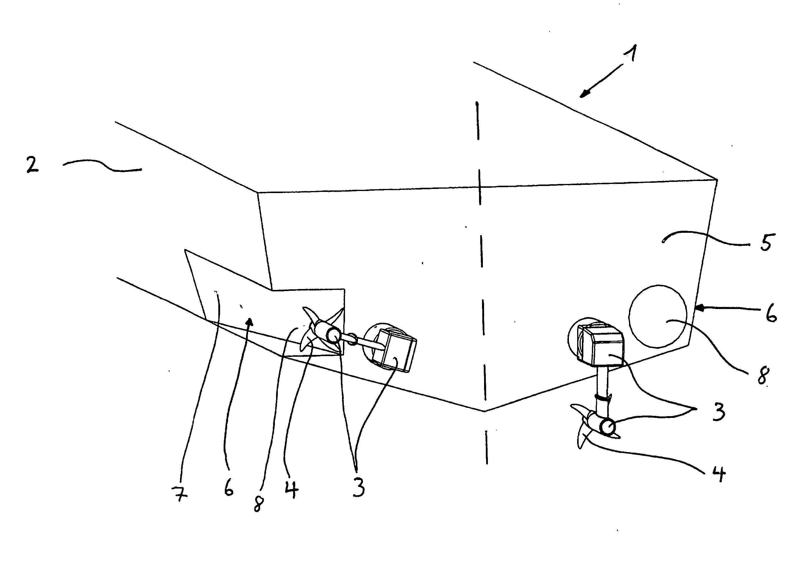
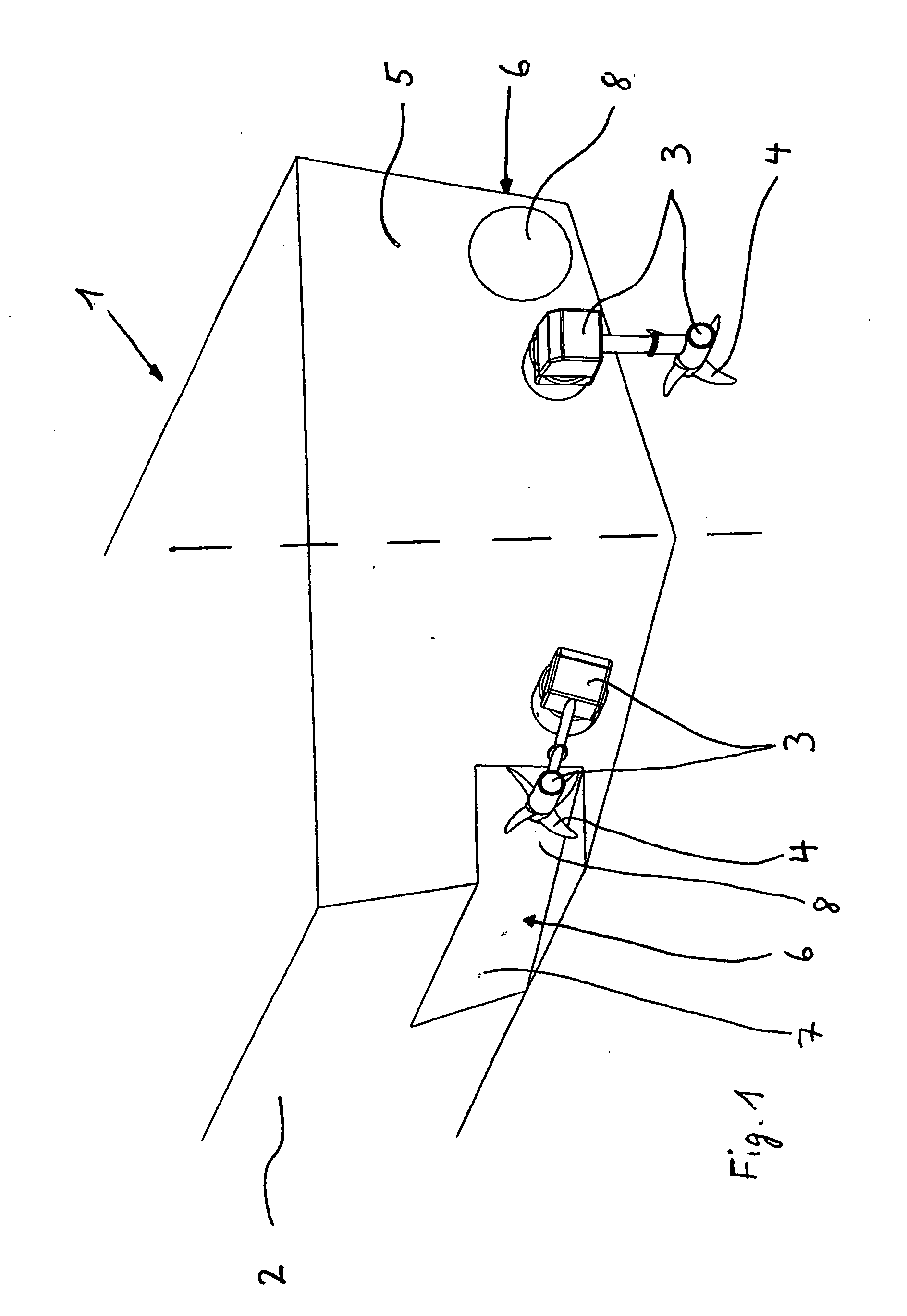
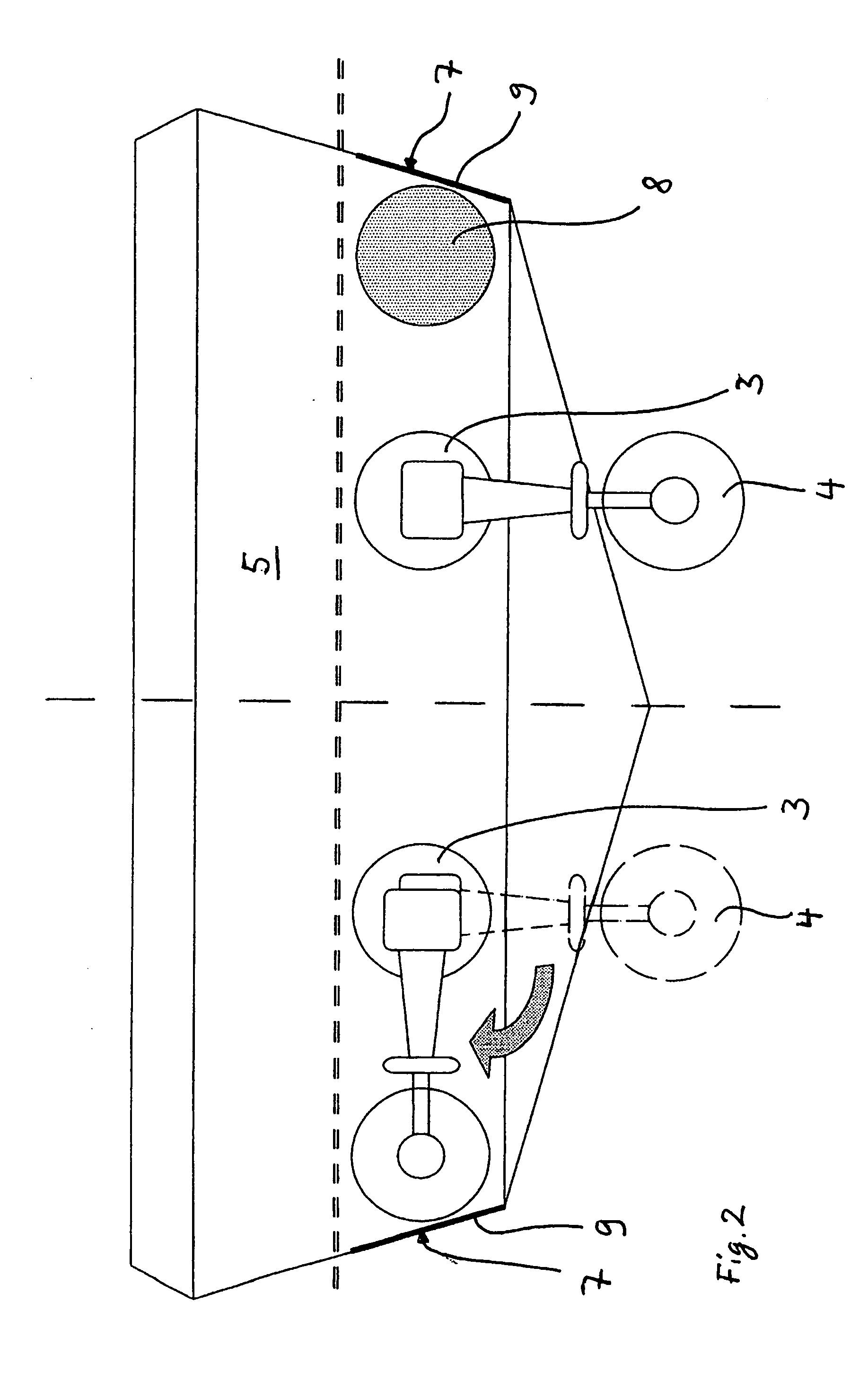
[0008] The core idea of the invention is, in other words, that at least one section of the underwater transmission and the propeller are able to be pivoted by certain means laterally relative to the watercraft.

[0009] The advantages of the invention involve, among other things, the fact that a radially pivotable underwater transmission allows for a space-saving underwater transmission having an unmodified thrust direction f...


PUM


Abstract

The invention relates to a watercraft comprising a hull, at least one motor which is fixed in or onto said hull, and a propeller which is driven by the motor by means of a transmission. According to the invention, at least part of the underwater transmission and the propeller can be laterally pivoted in relation to the watercraft by means of rotary elements.

Description

TECHNICAL FIELD [0001] The invention relates to a watercraft as specified in the preamble of the first claim. PRIOR ART [0002] Four different types of mounting designs for the propeller drive used in watercraft are known. First there is the underwater transmission for an outboard motor; secondly, there is the so-called Z-drive; in addition, there is the shaft system; and finally, there is the waveguide system within a pipe, known as a jet, wherein the propeller functions as a so-called impeller. These mounting designs are employed for corresponding propeller-thrust purposes, such as, for example, full-immersion, partial-immersion or surface propulsion, or reaction propulsion. [0003] The advantage of outboard motors and Z-drives is the fact that the underwater transmission, and thus the propeller, can be tilted backward and upward in the event the watercraft has entered shallow water, such that the propeller is prevented from striking the bottom and thus protected from being damaged....

Claims


Application Information

Patent Timeline
Patent Type & Authority Applications(United States)
IPC IPC(8): B63H20/08B63B43/18B63H5/125B63H5/16B63H20/10B63H20/18
CPCB63B43/18B63H5/16B63H20/08B63H20/10B63H20/18
Inventor MULLER, PETERA
Owner SUPRAVENTURES
Why Eureka
Try Eureka