
Wireless LAN handover method, wireless terminal, program product for use in the wireless terminal, and wireless communications system

a wireless terminal and handover technology, applied in the field of wireless communication system, can solve the problems of not preventing communication loss, increasing the load on the wireless network, etc., and achieve the effect of improving the network transmission efficiency and reliability, preventing re-transmission and loss of inbound packets

Inactive Publication Date: 2006-04-13
NEC CORP
View PDF6 Cites 82 Cited by
  • Summary
  • Abstract
  • Description
  • Claims
  • Application Information

AI Technical Summary

Benefits of technology

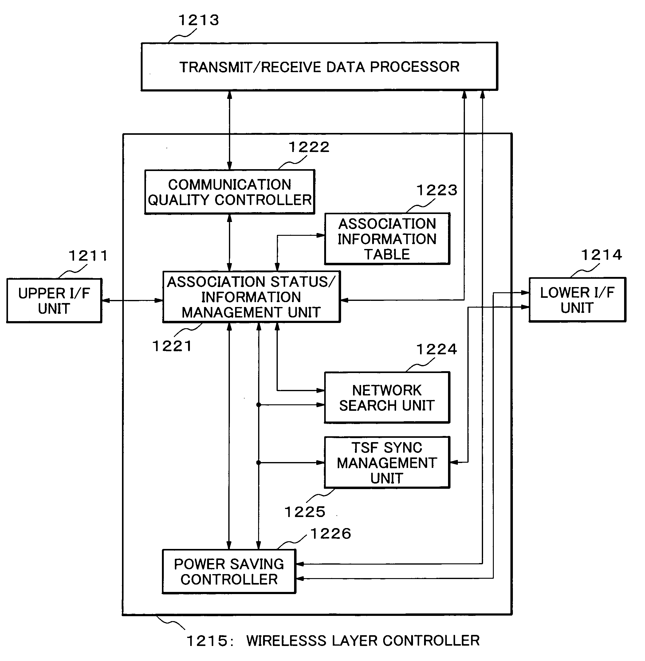
The present invention provides a technique for improving network transmission efficiency and reliability by preventing re-transmission and loss of inbound packets in the wireless segment when the currently associated terminal is searching for another BSS or IBSS. The handover method involves a wireless terminal associated with a BSS or IBSS searching for another BSS or IBSS, after having preliminarily notified its transition into power saving mode to the currently associated BSS or IBSS, or after having preliminarily and intentionally transited into power saving mode. To prevent loss of downlink data packets to the terminal in power saving mode, the base station stores the electric power management status of the terminal. When the terminal searches for another BSS or IBSS, the base station buffers downlink data packets and indicates the identifier of the terminal in the Traffic Indication Map (TIM) information of the beacon. The terminal requests transmission of the packets buffered in the base station, and the base station transmits these packets. The handover method provides advantages such as preventing loss of downlink packets, reducing network load due to wasteful re-transmissions, and avoiding dissolution of the terminal's association with the base station.

Problems solved by technology

However, these methods can not prevent communication loss which occurs during the search for a base station, an access point, or a wireless network.
Additionally, frequent search for an AP by the terminal increases the load on the wireless network.
The re-transmission increases the load on the wireless network.

Method used


Image

  • Wireless LAN handover method, wireless terminal, program product for use in the wireless terminal, and wireless communications system
  • Wireless LAN handover method, wireless terminal, program product for use in the wireless terminal, and wireless communications system
  • Wireless LAN handover method, wireless terminal, program product for use in the wireless terminal, and wireless communications system

Examples


embodiment 1

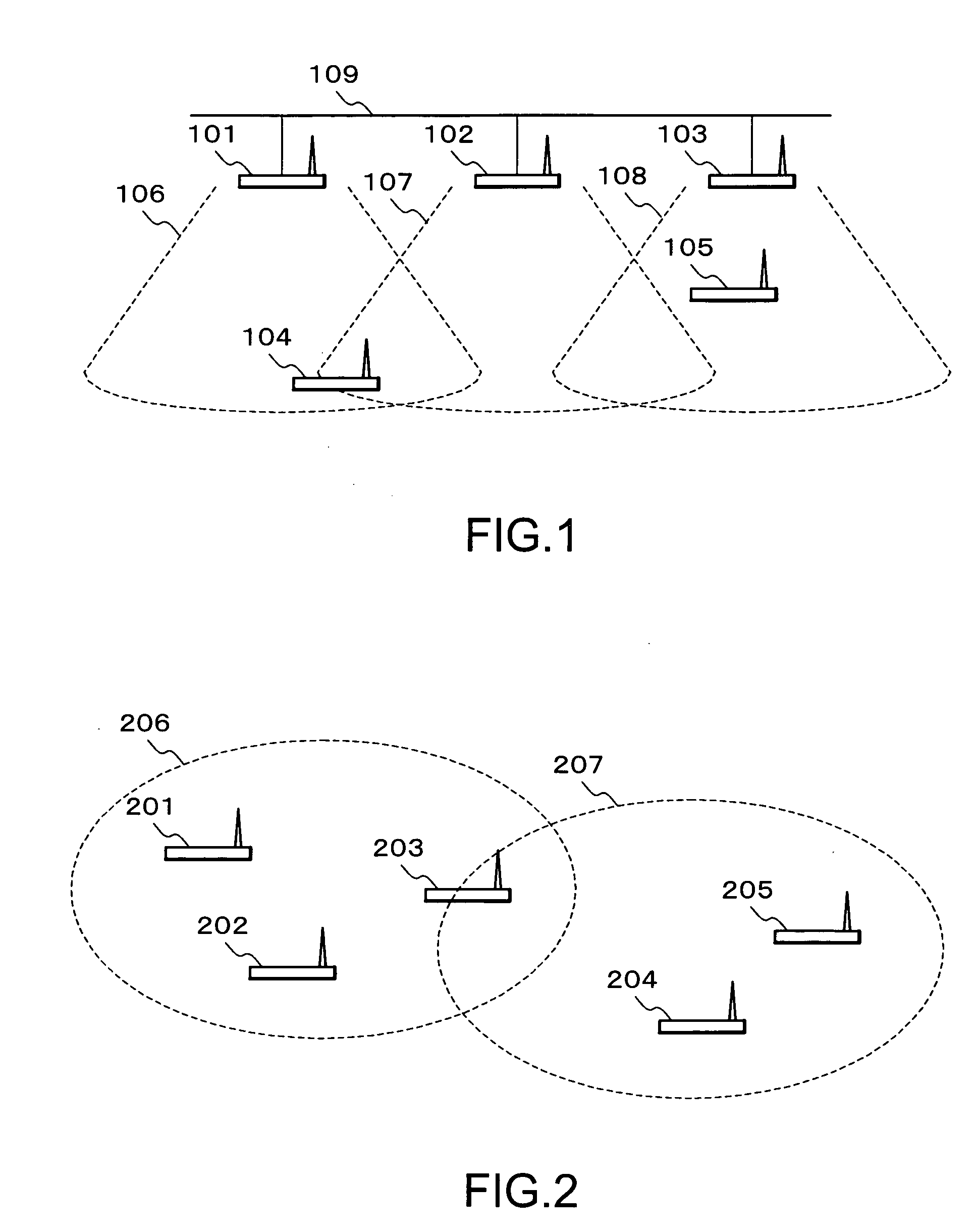
[0104] Embodiment 1 is an exemplary search for a new AP, in such a condition that the terminal 104 operating in infrastructure mode is already associated with AP 101. Here, in the present embodiment, active scan is used in the search for a new target to be associated with.

[0105]FIG. 12 illustrates how the terminal 104 already associated with AP 101 performs a search for AP 102 of FIG. 1. In FIG. 12, the horizontal axis represents time. The upward arrows represent signals transmitted by the terminal (uplink data packet) and downward arrows represent signals transmitted by the AP (downlink packet).

[0106] AP 101 and AP 102 periodically transmit beacons (B) 600 and 601 via different channels, respectively. In the present embodiment, the terminal 104 is associated with BSS 106 constituted with AP 101 as the core, and mainly receives downlink data packets. A packet 602 is a downlink data packet from AP101 to the terminal 104, and a packet 603 is a reception acknowledgement (ACK) returne...

embodiment 2

[0115] Embodiment 2 is another exemplary AP search performed under a condition such that the terminal 104 operating in infrastructure mode is communicating in association with AP 101. The search is performed by active scan also in this embodiment.

[0116]FIG. 13 illustrates how the terminal 104 of FIG. 1 performs a search for AP under a condition such that the terminal is communicating in association with AP 101. In FIG. 1, AP 101, AP 102, and AP 103 are communicating via different channels, respectively.

[0117] AP 101 and AP 102 periodically transmit beacons 700 and 701, which the terminal 104 is capable of receiving. On the other hand, since the terminal 104 is out of range where the radio wave of AP 103 reaches, as shown in FIG. 1, the terminal 104 cannot receive the beacon transmitted by AP 103.

[0118] The terminal 104 is associated with BSS 106 constituted with AP 101 as the core, and performs communication. Packets 702, 703, 704, and 705 represent, respectively, a downlink data...

embodiment 3

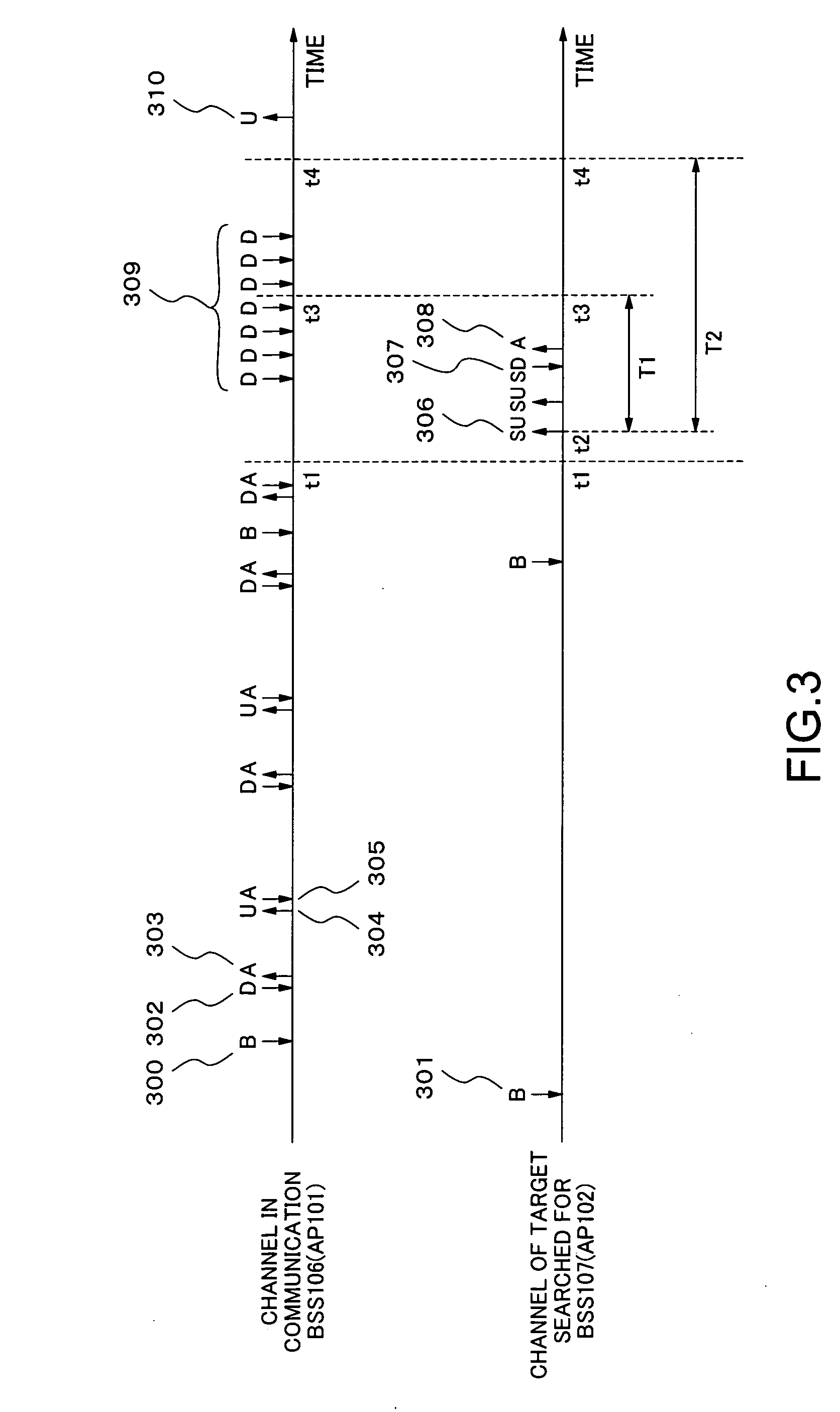
[0129] Embodiment 3 is an example wherein the terminal 104 of FIG. 1 operates in infrastructure mode and searches for AP using passive scan.

[0130]FIG. 14 illustrates signals which are exchanged between the terminal 104 of FIG. 1, and APs 101, 102 and 103.

[0131] AP 101 and AP 102 periodically transmit beacons 800 and 801. Since the terminal 104 is out of range where the radio wave of AP 103 reaches, as shown in FIG. 1, the terminal 104 cannot receive beacons from AP 103.

[0132] The terminal 104 is associated with BSS 106 constituted with AP 101 as the core, and performs communication. Packets 802, 803, 804, and 805 represent, respectively, a downlink data packet from AP 101 to the terminal 104, ACK for the downlink data packet 802, uplink data packet from the terminal 104 to AP 101, and ACK for the uplink data packet.

[0133] The terminal 104 migrates from the channel of AP 101 (channel currently in communication) to the channel of AP 102 from time point t1 for the searching. The te...


PUM


Abstract

A wireless terminal is associated with a Basic Service Set (BSS) or an Independent Basic Service Set (IBSS). The wireless terminal notifies the currently associated target of transition into power saving mode, before migrating from the currently associated BSS or IBSS to another BSS or IBSS. Subsequently, the wireless LAN terminal starts searching for another BSS or IBSS which is the next candidate target to be associated with.

Description

BACKGROUND OF THE INVENTION [0001] 1. Field of the Invention [0002] The present invention relates to a wireless communication system, and particularly to a wireless handover technique for wireless terminal having a power saving function. [0003] 2. Description of the Related Art [0004] When communication quality between a wireless terminal and a wireless base station degrades, the wireless terminal searches for another base station. Then, based on the search result, the wireless terminal is associated with another wireless base station having the best communication quality and continues the communication. Such a technique is referred to as handover. The handover technique is employed in cellular telephone systems, wireless LAN systems, or the like. [0005] As an approach to reduce communication loss when performing handover, a technique has been devised for reducing the time required for handover. The technique is described in JP-A 2004-207922 bulletin (Document 1) and JP-A 8-191305 (...

Claims


Application Information

Patent Timeline
Patent Type & Authority Applications(United States)
IPC IPC(8): H04Q7/20H04W36/08H04W52/02H04W84/12
CPCH04W36/0088H04W76/046H04W84/12H04W52/0216H04W52/0219Y02B60/50H04W76/27Y02D30/70
Inventor OMORI, YOUKOMORIMOTO, SHINICHI
Owner NEC CORP
Learn More