[0016] The attachment device may include additional features to enable the
insertion of the head end of the tension link into the
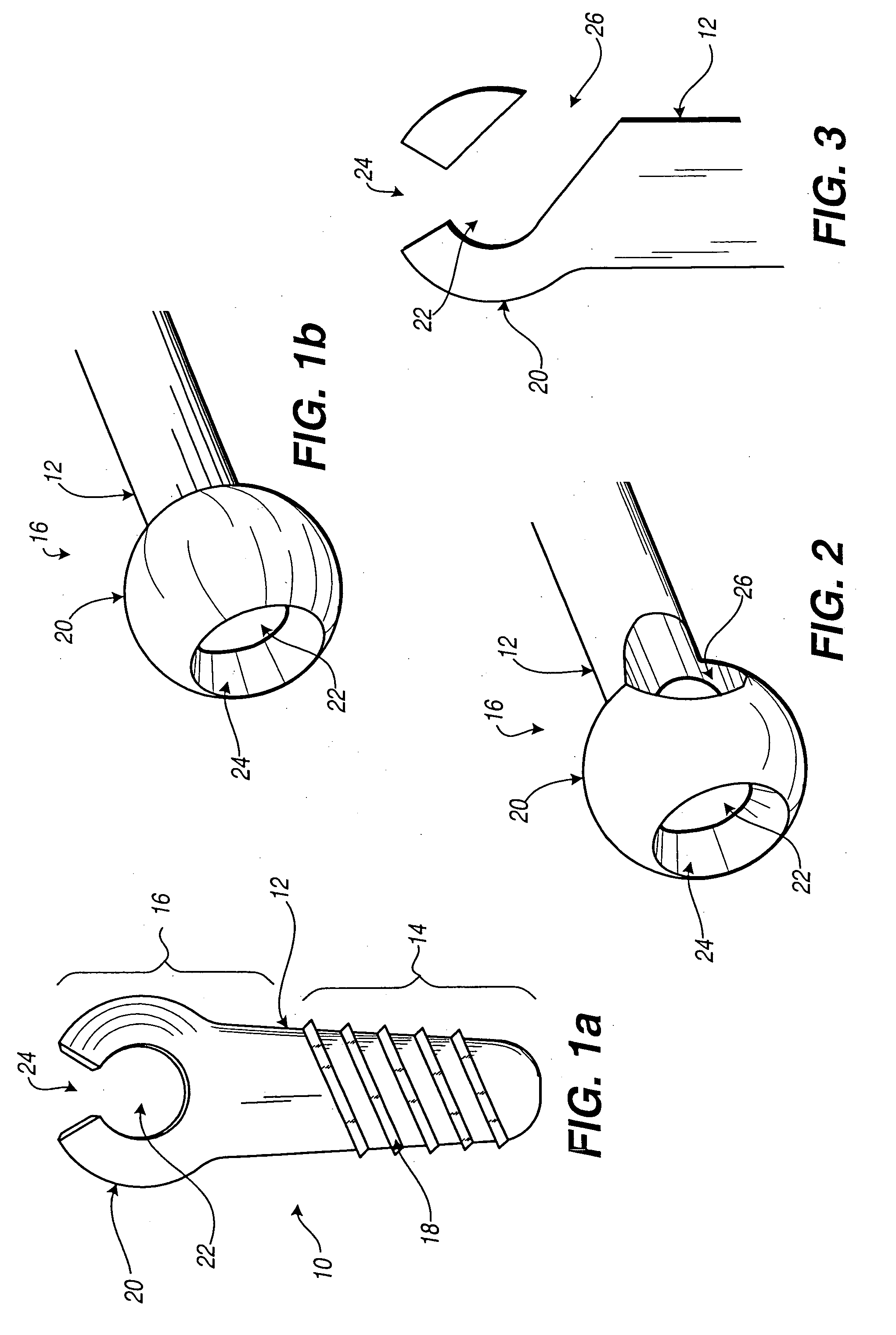
hollow core. The enlarged area of the attachment device may include an entry channel leading to the
hollow core that accommodates the tension link head end so that the tension link may be advanced, shaft end first, until the head of the tension link is positioned within the
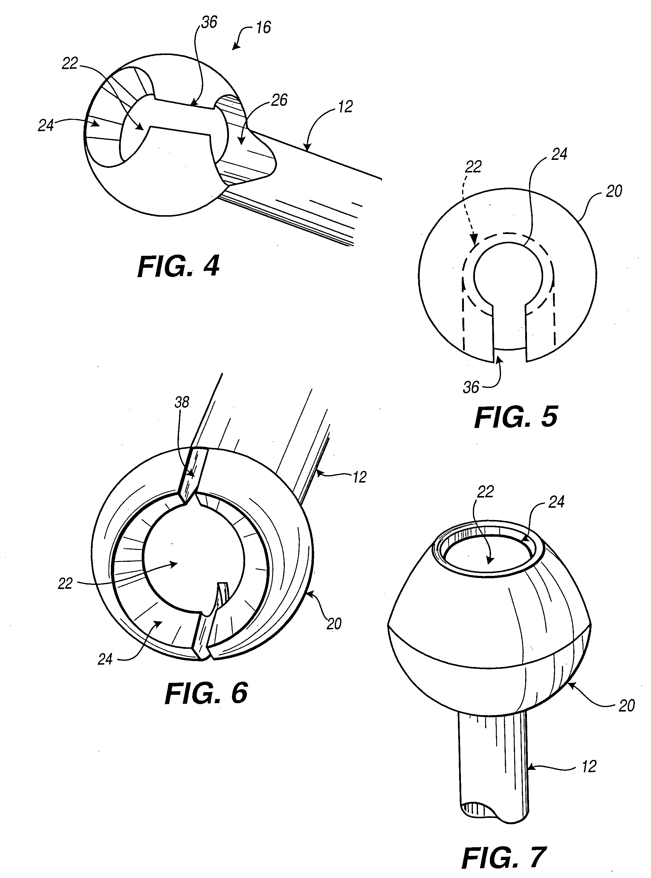
hollow core. Additionally, the entry channel and the central aperture may be connected by a slot through the wall of the enlarged area. In this way, the tension link head end may be positioned within the hollow core without extending the entire length of the tension link beyond the enlarged area of the attachment device opposite the central aperture. The surgeon may place only the head end of the tension link at the entry channel, slide the tension link shaft through the tension link slot, and draw the head end into the hollow core. Alternatively, in lieu of an entry channel or tension link slot, the enlarged area may include one or more expansion slots. In this embodiment, the head of the tension link may be inserted into the hollow core through the central aperture by the application of enough force to expand the central aperture. Once the head of the tension link is properly received into the hollow core, the enlarged area returns to its original size and shape. Unwanted expansion of the enlarged area is prevented by the connector once the enlarged area is properly seated into a head receptacle on the connector during implantation. This maintains the head of the tension link within the hollow core.
[0019] The tension link may be provided with a projection to prevent undesirable rotation of the link when tightening or loosening the link nut, yet still enable
angular displacement necessary to provide a polyaxial connection. In one embodiment, a link
retainer, or a projection, may be provided on the shaft of the tension link. In this embodiment, it is necessary to provide a link
retainer recess within the tension link cavity of the connector. In an alternative embodiment, the link
retainer, or projection, may be provided at the intersection of the tension link shaft and the head end, and extending over a portion of the surface of the head end. In this embodiment, used with the attachment device embodiment including a tension link slot, the rotation may be prevented by contacting the link retainer with one side of the tension link slot. In either of the two foregoing embodiments, it is desirable to undersize the link retainer, relative to the link retainer recess or the tension link slot, so that the polyaxial freedom of the tension link and attachment device combination is not unduly limited. In an alternative embodiment, a retaining process, or small projection, may be provided on the tension link head. The retaining process should be positioned such that the retaining process is within the entry channel. Undesired rotation may be prevented by contacting the small projection with the wall of the entry channel.
[0022] In either of the two foregoing connector embodiments, it may be desirable to secure the rod within the rod aperture without clamping to the extent axial movement of the rod within the rod aperture is prevented. In this way, for example, the spine may settle under its own weight and provide a better healing environment for the bone. In conjunction with this embodiment, the implant component may be supplied with flanges, or other extensions to constrain axial movement of the implant component within a desired range.
[0024] Based on the foregoing summary, a number of worthwhile aspects of the present invention can be readily identified. An attachment device is provided with a small and simple polyaxial adjustment mechanism. The minimal size of the enlarged area of the attachment device allows attachment of the device to
human bone without significant displacement of human tissue. Therefore, the complexity of
surgery and the following pain and discomfort of the patient may be minimized. The polyaxial nature of the device, combined with the small size, may allow a surgeon to attach the securement device to a secure portion of the
human body without the need to remove bony processes to accommodate a larger attachment device. Additionally, a simple
surgical implant assembly, including the polyaxial attachment device, is provided. The simplicity of the elements, and the assembly process thereof, may reduce the patient's time in surgery, thus reducing the risk and probability of surgical complications. Finally, a number of embodiments of the present invention may be used in combination to allow the surgeon great
latitude in selection of materials. The surgeon may select from different embodiments of the attachment device, the tension link, and the connector to best fit the
surgical implant parameters. With these choices the surgeon may then best determine which embodiments of which elements to select to minimize removal or displacement of bodily tissue or bone, and thereby reduce both the patient's risk of surgical complications and post-
surgical pain and discomfort.
[0030] A method of use is also presented for the clamp device, wherein in a preferred embodiment the two attachment devices are installed by advancing an attachment device into each of two bone segments. The hollow core of each attachment device is then fitted with a the head of a tension link. Alternately, the tension link may be inserted into the hollow core of the tension link prior to
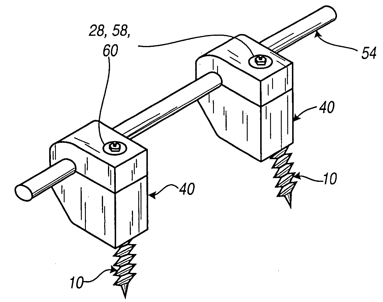
insertion of the attachment devices into bone. After the attachment devices with their respective tension links are in place, one of the attachment devices is fitted with an interior rod member that includes a rod portion and an end connector in the form of a receptacle shaped like a socket. The socket includes a tension link cavity such that the shaft of the tension link is passed through the tension link cavity as the socket is being placed over the enlarged area of the first attachment device. A clamp comprising a lower and upper clamp portion is then assembled to grasp the rod portion of the interior rod member as the upper and lower clamp are connected to the second attachment device by passing the shaft of the second tension link through tension link cavities in the securing ends of the lower and upper clamp portions. Link nuts are then threaded on to exposed ends of the tension link shafts and are tightened. The position of the interior rod member can be adjusted within the clamp as the link nuts are tightened, thereby allowing the surgeon to adjust the size of the assembly to accommodate the patient's needs for a customized fit. The assembly minimizes the need to create a large incision because implantation work can be substantially performed from a direction perpendicular to the bone segments. Furthermore, this low profile assembly is relatively simple to install, thereby reducing surgery time over existing stabilizing devices.

