

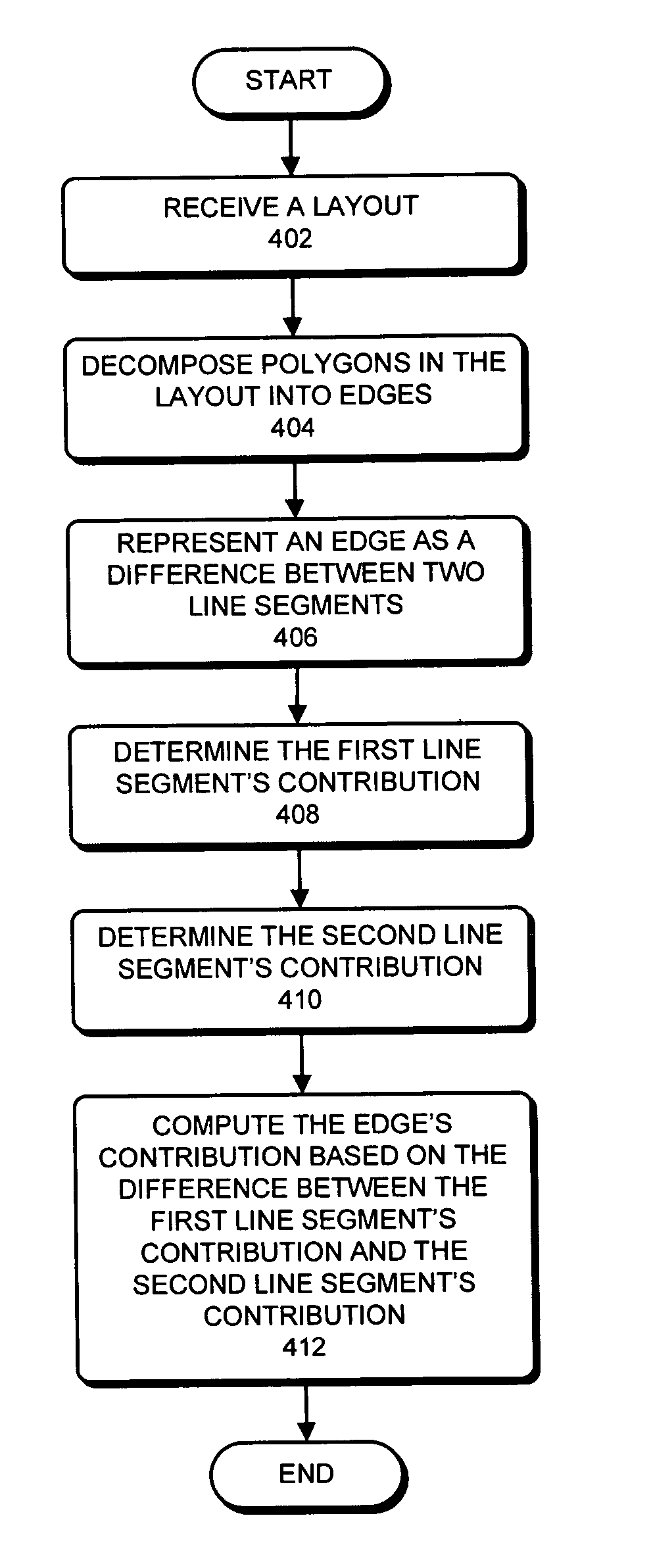
Edge-based proximity correction
a proximity correction and edge technology, applied in the field of semiconductor manufacturing processes, can solve the problems of inability to find exact analytical formulae to predict, largely insensitive to the specific positioning of polygons relative to one, and it is becoming progressively harder to accurately predict and correct undesirable effects of semiconductor manufacturing processes using linear-convolution based techniques
- Summary
- Abstract
- Description
- Claims
- Application Information
AI Technical Summary
Benefits of technology
Problems solved by technology
Method used
Image

Examples
Embodiment Construction
Integrated Circuit Design and Fabrication
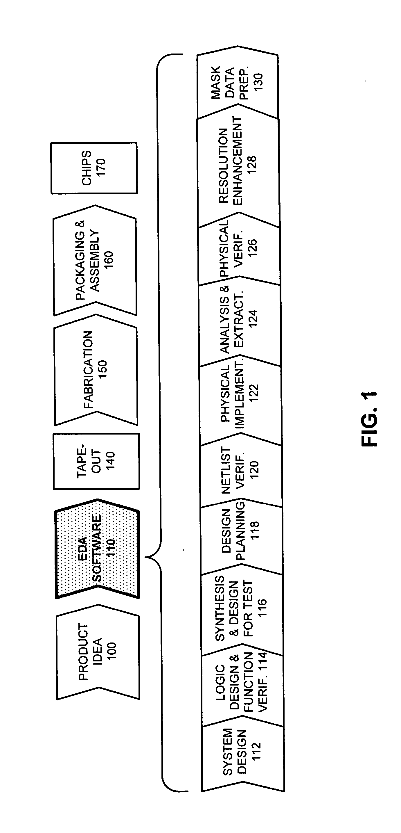
[0023]FIG. 1 illustrates various steps in the design and fabrication of an integrated circuit in accordance with an embodiment of the present invention. The process starts with a product idea (step 100). Next, the product idea is realized using an integrated circuit, which is designed using Electronic Design Automation (EDA) software (step 110). Once the circuit design is finalized, it is taped-out (step 140). After tape-out, the process goes through fabrication (step 150), packaging, and assembly (step 160). The process eventually culminates with the production of chips (step 170).
[0024] The EDA software design step 110, in turn, includes a number of sub-steps, namely, system design (step 112), logic design and function verification (step 114), synthesis and design for test (step 116), design planning (step 118), netlist verification (step 120), physical implementation (step 122), analysis and extraction (step 124), physical verification ...
PUM
 Abstract
Description
Claims
Application Information