Falling film evaporator

a technology of falling film and evaporator, which is applied in the direction of indirect heat exchangers, refrigeration components, light and heating apparatus, etc., can solve the problems of reduced efficiency of evaporator, and loss of whole charge of refrigerant, so as to prevent cross flow, facilitate increased heat transfer, and reduce the effect of recirculation ra

Active Publication Date: 2006-04-20
JOHNSON CONTROLS TYCO IP HLDG LLP
View PDF80 Cites 35 Cited by
  • Summary
  • Abstract
  • Description
  • Claims
  • Application Information

AI Technical Summary

Benefits of technology

[0017] An advantage of the present invention is that it substantially prevents cross flow caused by expanding vaporizing fluid, facilitating increased heat transfer with a minimum re-circulation rate.
[0018] A still further advantage of the present invention is that provides an efficient means of avoiding the carry-over of liquid droplets into the compressor suction.
[0019] A still further advantage of the present invention is that it is easy to manufacture and install.
[0020] A still yet further advantage of the present invention is that it can accommodate a mix of liquid and vapor at moderate or high pressure that is applied by the distributor over the tube bundle.
[0021] A further advantage of the present invention is that it can be used with either a falling film evaporator construction or a hybrid falling film evaporator construction.
[0022

Problems solved by technology

Therefore, a considerable amount of the refrigerant fluid is required, which is costly to provide, and may be an environmental and/or safety concern, depending upon the composition of the refrigerant, in case of leakage of the refrigerant from the evaporator or from the whole system, in which the whole charge of refrigerant may be lost.
However, there are technical challenges associated with the efficient operation of the falling film evaporator.
One challenge is that a portion of the fluid vaporizes and significantly expands in volume.
Due to the cross flow disrupting the vertical flow of the fluid, at least a portion of the tubes, especially the lower positioned tubes of the tube bundle, receive insufficient wetting, providing significantly reduced

Method used


Image

  • Falling film evaporator
  • Falling film evaporator
  • Falling film evaporator

Examples


Embodiment Construction

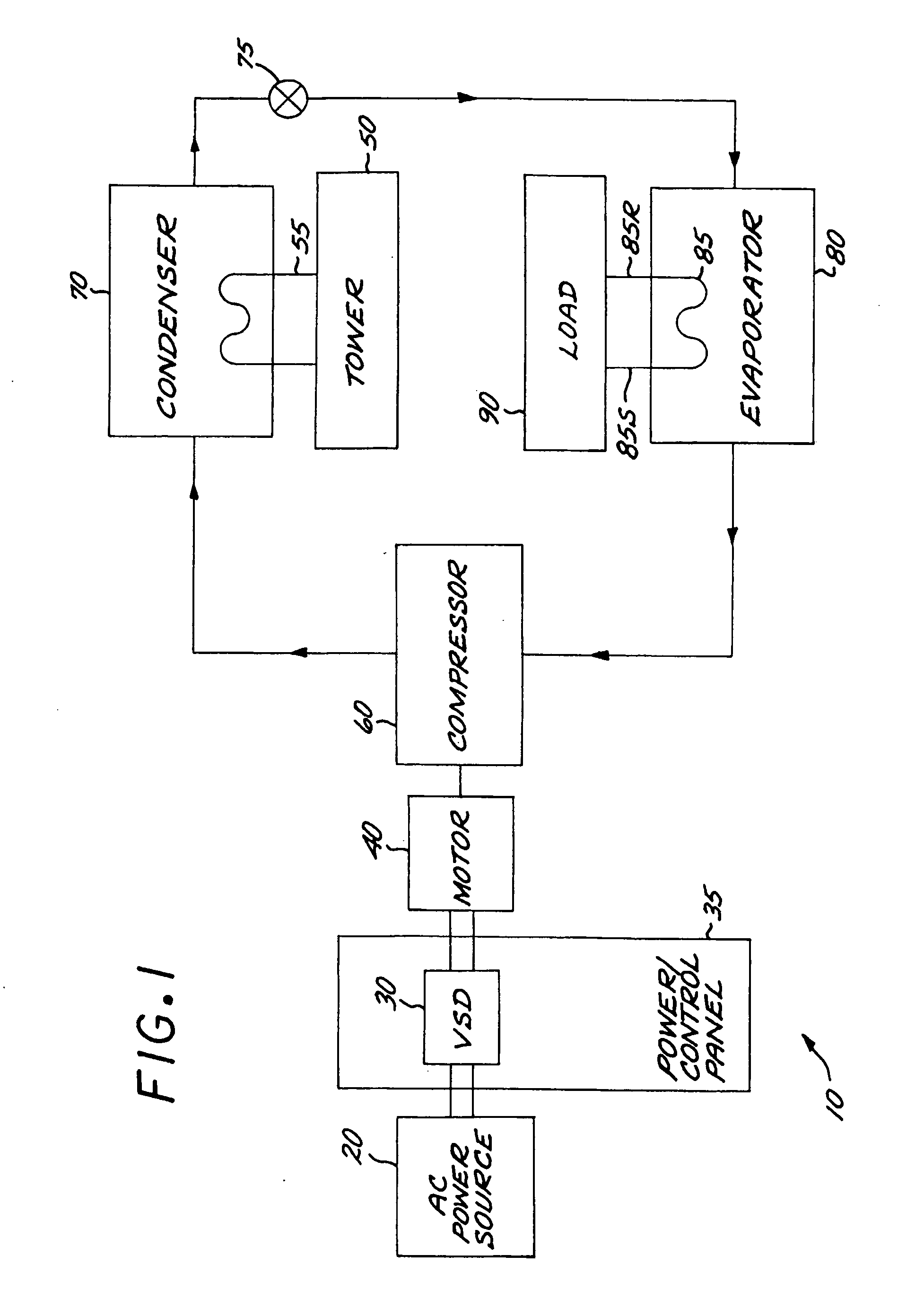
[0029]FIG. 1 illustrates generally one system configuration of the present invention. A refrigeration or chiller system 10 includes an AC power source 20 that supplies a combination variable speed drive (VSD) 30 and power / control panel 35, which powers a motor 40 that drives a compressor 60, as controlled by the controls located within the power / control panel 35. It is appreciated that the term “refrigeration system” can include alternate constructions, such as a heat pump. In one embodiment of the invention, all of the components of the VSD 30 are contained within the power / control panel 35. The AC power source 20 provides single phase or multi-phase (e.g., three phase), fixed voltage, and fixed frequency AC power to the VSD 30 from an AC power grid or distribution system that is present at a site. The compressor 60 compresses a refrigerant vapor and delivers the vapor to the condenser 70 through a discharge line. The compressor 60 can be any suitable type of compressor, e.g., cent...


PUM


Abstract

A falling film evaporator is provided for use in a two-phase refrigeration system or process system. The evaporator includes a shell having an upper portion, a lower portion, and a tube bundle having tubes extending substantially horizontally in the shell. A hood is disposed over the tube bundle, the hood having an upper end adjacent the upper portion above the tube bundle, the upper end having opposed substantially parallel walls extending toward the lower portion, the walls terminating at an open end opposite the upper end. Once liquid refrigerant or liquid refrigerant and vapor refrigerant is deposited onto the tube bundle, the substantially parallel walls of the hood substantially prevent cross flow of refrigerant vapor or liquid and vapor between the tubes of the tube bundle.

Description

BACKGROUND OF THE INVENTION [0001] The present invention relates generally to the operation of an evaporator in a heating and cooling system or process system, and more specifically, to the operation of a falling film evaporator in a two-phase refrigerant heating and cooling system or process system. [0002] Certain process systems, as well as heating and cooling systems for buildings or other structures that typically maintain temperature control in a structure, circulate a fluid within coiled tubes such that passing another fluid over the tubes effects a transfer of thermal energy between the two fluids. A primary component in such a heating and cooling system is an evaporator that includes a shell with a plurality of tubes forming a tube bundle through which a secondary fluid, such as water or ethylene glycol, is circulated. A primary fluid or refrigerant, such as R134a, is brought into contact with the outer or exterior surfaces of the tube bundle inside the evaporator shell resu...

Claims


Application Information

Patent Timeline
IPC IPC(8): F25B39/02F28F9/22F25B41/06F28D7/00
CPCF25B39/028F25B2339/0242F25B2341/0011F28D3/02F28F9/0265F28F9/22F28F13/187F25B39/02F28F27/02
Inventor DE LARMINAT, PAULLE COINTE, LUCJUDGE, JOHN FRANCISKULANKARA, SATHEESH
Owner JOHNSON CONTROLS TYCO IP HLDG LLP
Why Eureka
Try Eureka