Thermal management of dielectric components in a plasma discharge device

a technology of dielectric components and plasma discharge devices, which is applied in the direction of electric discharge tubes, coatings, metal material coating processes, etc., can solve the problems of high internal stress of dielectric components, difficult thermal management, and limiting the performance, range, reliability, or other operating characteristics of plasma devices, etc., to achieve convenient heat extraction, improve heat extraction uniformity, and low viscosity

Inactive Publication Date: 2006-04-20
ADVANCED ENERGY IND INC
View PDF22 Cites 16 Cited by
  • Summary
  • Abstract
  • Description
  • Claims
  • Application Information

AI Technical Summary

Benefits of technology

[0010] In one embodiment of the invention, a plasma source apparatus comprises a cylindrical plasma discharge tube that confines a plasma within. A helical coil constructed of square metal tubing is disposed coaxially about the outer surface of the dielectric discharge tube. The inward facing flat surfaces of the helical coil are in substantially direct and uniform contact with the outer surface of the dielectric discharge tube. A cooling fluid is flowed through the helical coil to extract heat transferred from the discharge tube to the metal coil. The turns of the cooling coil are spaced apart and electrically connected to an RF power source, thus allowing the cooling coil to function also as an inductive winding that couples RF power into the plasma within the discharge tube.
[0012] In another aspect of the invention, the cooling instrument of a plasma discharge device is embedded within an encapsulation material that enhances the uniformity of heat extraction from a dielectric plasma chamber. The encapsulation material preferably has a low viscosity so as to displace residual air pockets between the dielectric chamber and the cooling instrument, along with a thermal conductivity that facilitates heat extraction from the chamber.
[0013] By improving the uniformity of heat extraction from the dielectric chamber of a plasma discharge device, the invention reduces hot spots within the chamber wall during operation that would limit the performance and reliability of the device. As a result, the features of the invention permit safe and reliable operation of a plasma discharge device at significantly improved power levels.

Problems solved by technology

A persistent challenge in the engineering of plasma discharge devices is control and removal of heat generated by the plasma.
The ability of materials exposed to a plasma to withstand the thermal environment of the discharge often significantly restricts the performance, range, reliability, or other operating characteristics of a plasma device.
Problems of thermal management are especially difficult in devices having dielectric materials in proximity to the plasma, particularly for structural purposes, owing to the poor thermal conductivity of most dielectrics.
While certain dielectric materials such as ceramics may be tolerant of elevated temperatures in bulk, hot spots resulting from non-uniform cooling can lead to high internal stresses in dielectric components due to differential thermal expansions.
It is not uncommon for these temperature-induced stresses to result in cracks in dielectric materials, leading in turn to premature failure of the plasma device.
For some applications, however, this approach presents an unacceptable risk that cooling fluid could enter the plasma chamber in the event of a break or crack and catastrophically contaminate processes occurring in or downstream of the chamber.
A conformal cooling jacket may also impede the ability to provide inductive coupling of electromagnetic energy into the plasma unless the cooling jacket assembly itself and the cooling fluid therein are themselves dielectric.
Even where a plasma chamber has a relatively simple geometry, however, such as a cylinder, providing a metal cooling coil that is exactly conformal to the surface of the chamber is a manufacturing challenge.
For example, a cooling coil that is prefabricated to have an inner major diameter larger that the outer diameter of the plasma chamber will be easy to assemble, but the gaps that necessarily exist between the coil and chamber wall will impair the uniformity and resistance of heat transfer from the chamber body to the cooling medium.
On the other hand, a prefabricated coil having near-zero tolerance to the outer chamber wall will be difficult to mate to the chamber, and forced assembly of the article can still result in bunching or gapping of the coil along the length of the chamber as well as damage to the chamber wall.
If the coil is not prefabricated but instead wound in place around the plasma tube, imperfect contact invariably results due to eccentricity of the winding and relaxation of the coil.
Even small gaps resulting from these manufacturing imperfections lead to uneven cooling of the dielectric chamber, and consequently to hot spots in the chamber walls that limit the performance and reliability of the device.
This process can also crack or damage the chamber during the manufacturing process.

Method used


Image

  • Thermal management of dielectric components in a plasma discharge device
  • Thermal management of dielectric components in a plasma discharge device
  • Thermal management of dielectric components in a plasma discharge device

Examples


Embodiment Construction

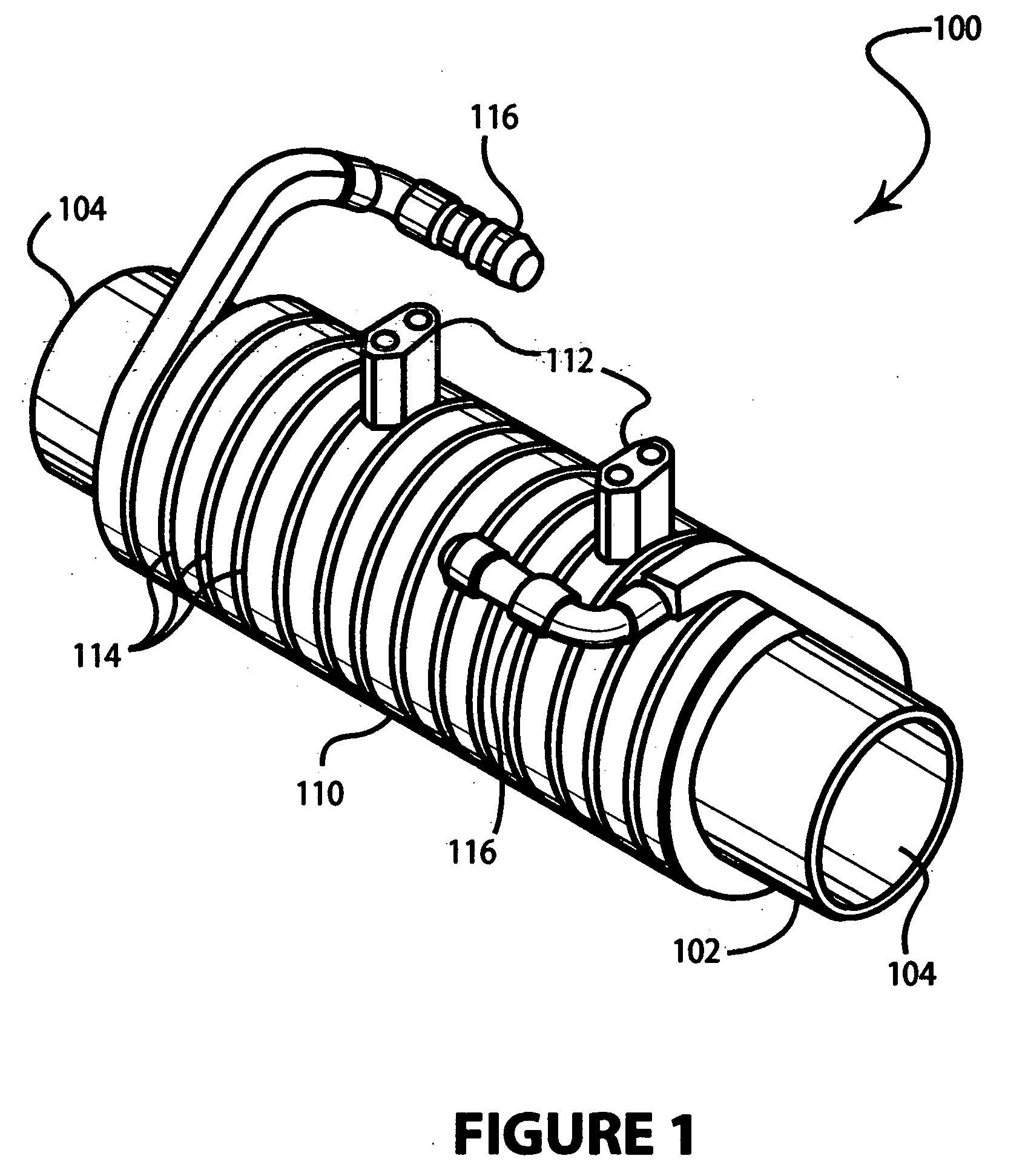
[0017]FIG. 1 illustrates a plasma source device in accordance with one embodiment of the invention. Plasma source 100 comprises cylindrical discharge tube 102 containing a plasma within. Discharge tube 102 is constructed substantially of a dielectric material such as quartz, alumina, aluminum nitride, or other structural dielectric suitable to the chemistry of the discharge environment within the tube. Discharge tube 102 is open at both ends 104 to allow for gas inlet and exhaust, as for example in an inline gas processing application. Alternatively, the plasma tube may be configured as a sealed vacuum chamber having metered inlet and exhaust ports for feed and processing gases. Not shown are other features that may typically be included in a plasma processing device such as vacuum pumping manifolds, gas delivery connections or manifolds, plasma ignition electrodes or other devices, and mechanisms for workpiece mounting, transfer, or electrical biasing.

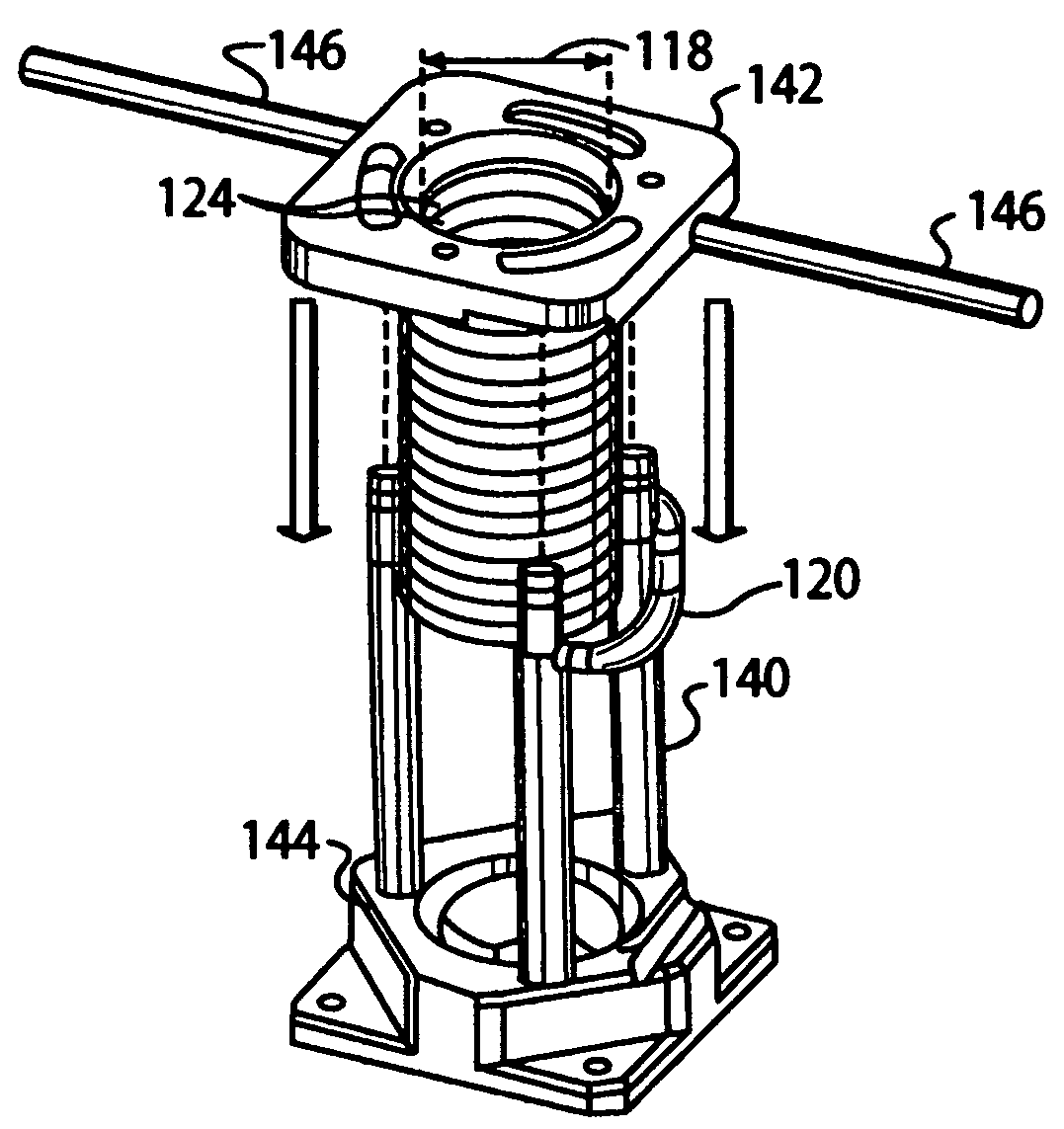
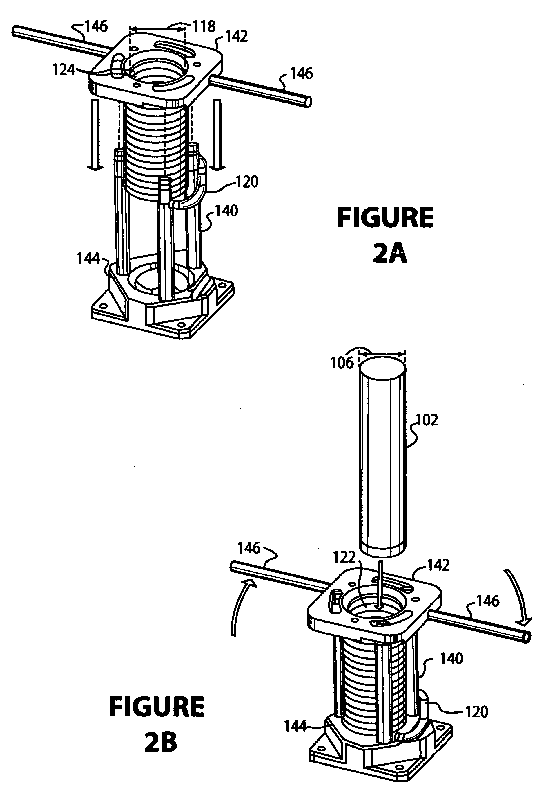
[0018] Disposed coaxially abo...


PUM

PropertyMeasurementUnit
diameteraaaaaaaaaa
dielectricaaaaaaaaaa
residual compressive forceaaaaaaaaaa

Abstract

A plasma discharge device is provided having features for enhanced thermal management and protection of dielectric materials in the device. The invention generally comprises a plasma confinement chamber constructed at least in part of dielectric materials, with a cooling instrument disposed in contact with the outer dielectric surfaces of the chamber for substantially uniform heat extraction. The cooling instrument may be embedded within an encapsulating material that enhances the uniformity of heat extraction from a dielectric plasma chamber. By improving the uniformity of heat extraction from the dielectric chamber of a plasma discharge device, the invention permits reliable operation of a plasma discharge device at significantly improved power levels.

Description

BACKGROUND OF THE INVENTION [0001] 1. Field of the Invention [0002] This invention relates generally to plasma discharge devices, and more particularly to thermal management and protection of dielectric materials in a plasma discharge device. [0003] 2. Brief Description of the Prior Art [0004] A persistent challenge in the engineering of plasma discharge devices is control and removal of heat generated by the plasma. The ability of materials exposed to a plasma to withstand the thermal environment of the discharge often significantly restricts the performance, range, reliability, or other operating characteristics of a plasma device. Problems of thermal management are especially difficult in devices having dielectric materials in proximity to the plasma, particularly for structural purposes, owing to the poor thermal conductivity of most dielectrics. While certain dielectric materials such as ceramics may be tolerant of elevated temperatures in bulk, hot spots resulting from non-uni...

Claims


Application Information

Patent Timeline
Patent Type & Authority Applications(United States)
IPC IPC(8): C23C16/00
CPCH01J37/321H01J37/32522C23C16/00
Inventor MAUCK, JUSTINDILLON, STEVEGONZALEZ, JUAN JOSESHABALIN, ANDREW
Owner ADVANCED ENERGY IND INC
Why Eureka
Try Eureka