Precision measurement unit having voltage and/or current clamp power down upon setting reversal

a technology of voltage and/or current clamping and precision measurement, which is applied in the direction of measurement devices, electronic circuit testing, instruments, etc., can solve problems such as damage to parts

Inactive Publication Date: 2006-04-20
SEMTECH CORP
View PDF4 Cites 12 Cited by
  • Summary
  • Abstract
  • Description
  • Claims
  • Application Information

AI Technical Summary

Benefits of technology

[0007] The present invention overcomes the drawbacks of the prior art by providing a precisi...

Problems solved by technology

But, if the user inadvertently reverses the programming of the clamp HLV and LLV parameters, i.e., progr...

Method used


Image

  • Precision measurement unit having voltage and/or current clamp power down upon setting reversal
  • Precision measurement unit having voltage and/or current clamp power down upon setting reversal
  • Precision measurement unit having voltage and/or current clamp power down upon setting reversal

Examples


Embodiment Construction

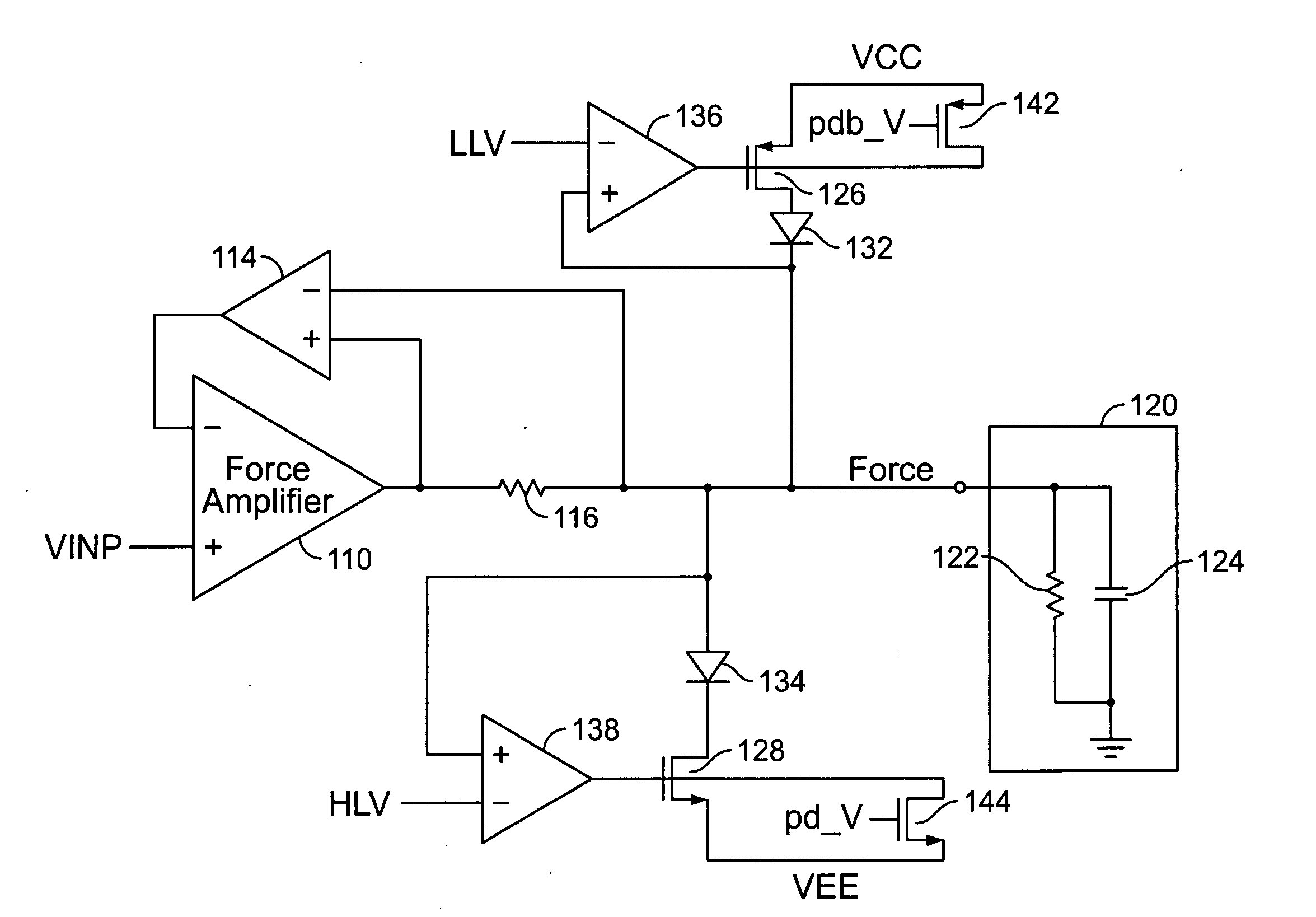
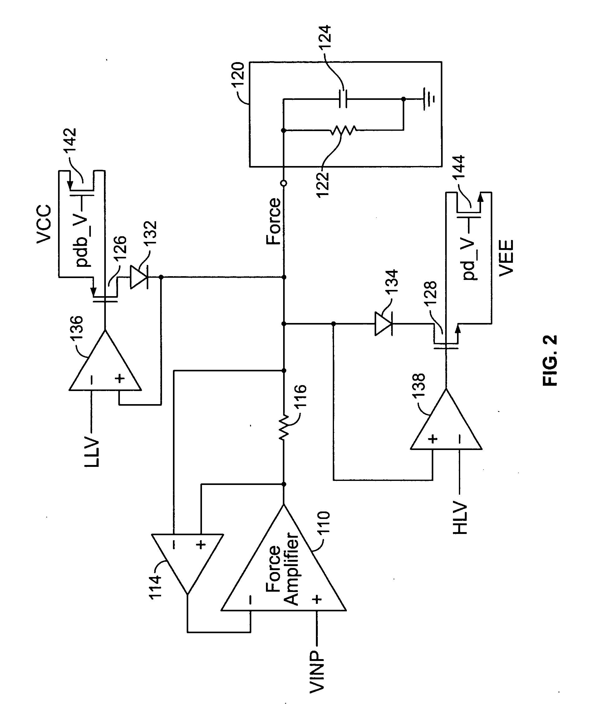
[0015] The present invention is directed to a PMU device having clamps that limit voltage or current spikes to a DUT and that protects against inadvertent reversal of the clamp range settings. It should be appreciated that like element numerals are used to describe like elements illustrated in one or more of the figures.

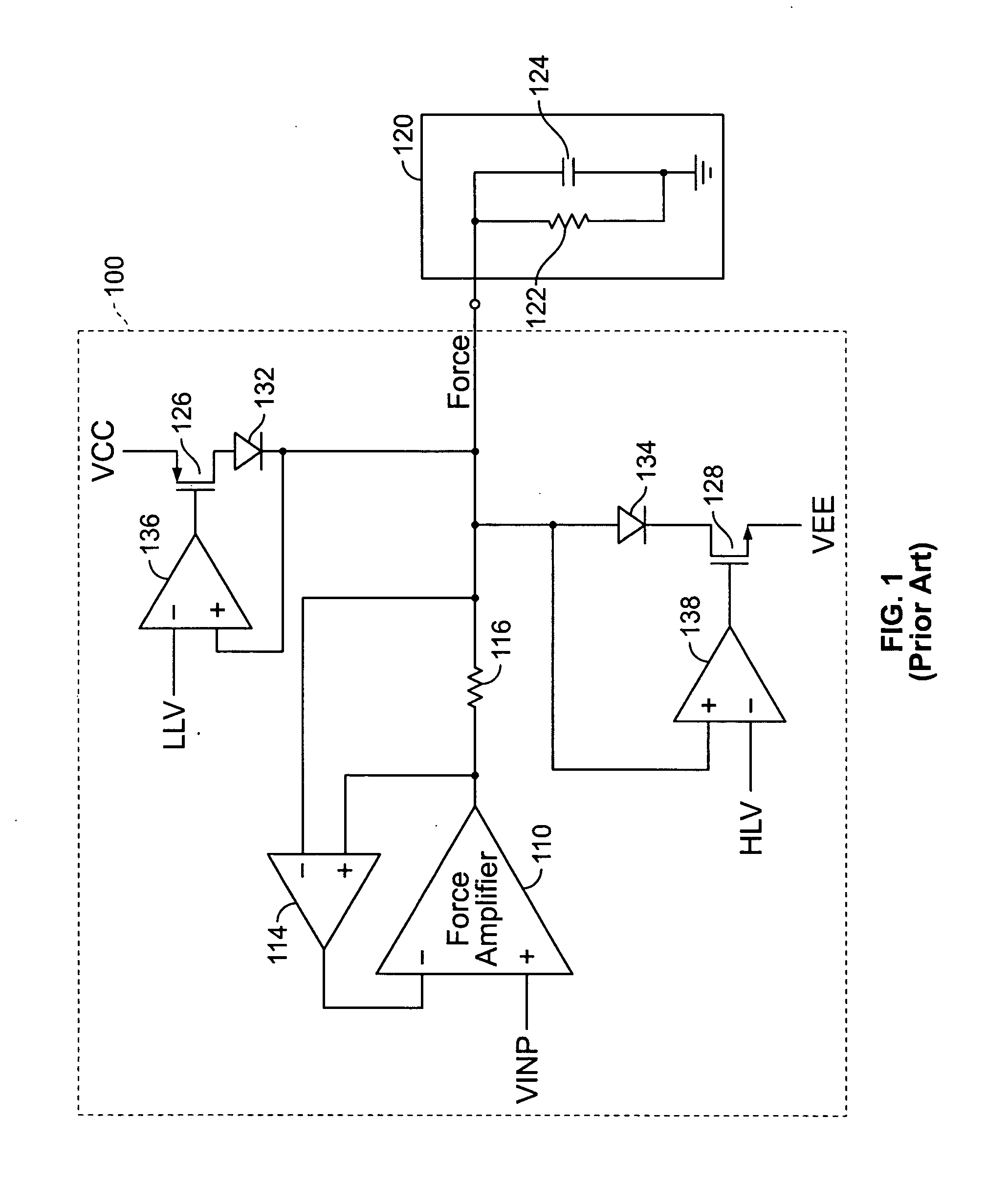
[0016]FIG. 1 illustrates a prior art precision measurement unit (PMU) 100 coupled to a DUT 120. The DUT 120 is illustrated as having a characteristic resistance 122 and capacitance 124. The PMU 100 includes a force amplifier 110 having two inputs and producing a force output. The force output is an analog output signal that either forces a current or forces a voltage, depending upon which operating mode of the PMU is selected. A current sense resistor 116 is connected in series with the force output. A current sense amplifier 114 has input terminals connected to either end of the current sense resistor 116 in order to sense the voltage drop across the current sense ...


PUM


Abstract

A precision measurement unit (PMU) includes a force amplifier selectively providing either a forcing voltage or a forcing current to a device under test via an output force terminal. A low limit voltage clamp and a high limit voltage clamp are operatively coupled to the output force terminal. The low and high limit voltage clamps are each responsive to user programming to define respective low and high voltage limits at the output force terminal. Upon detection of a reversal of said user programming, the operation of the low and high limit voltage clamps is disabled. More particularly, a comparator is adapted to compare the low and high voltage limits and provide a corresponding disabling signal if the high voltage limit is lower than the low voltage limit.

Description

BACKGROUND OF THE INVENTION [0001] 1. Field of the Invention [0002] The invention relates to the field of automatic test equipment for semiconductor devices, and more particularly to a precision measurement unit having clamps that limit voltage or current spikes to a device under test and that protects against inadvertent user reversal of the clamp range settings. [0003] 2. Description of Related Art [0004] As part of the manufacturing process, semiconductor devices are subjected to various tests in order to identify faults. This testing can occur at multiple points in the manufacturing process, including testing done before packaging and testing done after packaging. Manufacturer testing of semiconductors is often performed using equipment referred to as automatic test equipment, or ATE. An ATE system can be used in a wide variety of applications, including the identification of defective semiconductors and the sampling of parts for quality control. [0005] Automatic test equipment ...

Claims


Application Information

Patent Timeline
IPC IPC(8): G01R31/28
CPCG01R19/00
Inventor CHOW, CHUNG-KAI
Owner SEMTECH CORP
Why Eureka
Try Eureka