Audio processing

a technology of audio signal and processing, applied in the direction of stereophonic arrangments, transducer details, electrical transducers, etc., can solve the problems of reducing the filter count, reducing the filter headroom requirement, and avoiding overload, so as to reduce hardware cost and complexity, reduce the filter count, and reduce the cost

a technology of audio signal and processing, applied in the direction of stereophonic arrangments, transducer details, electrical transducers, etc., can solve the problems of reducing the filter count, reducing the filter headroom requirement, and avoiding overload, so as to reduce hardware cost and complexity, reduce the filter count, and reduce the cost

US20060083381A1Active Publication Date: 2006-04-20CIRRUS LOGIC INC

Image

  • Audio processing
  • Audio processing
  • Audio processing

Examples


Embodiment Construction

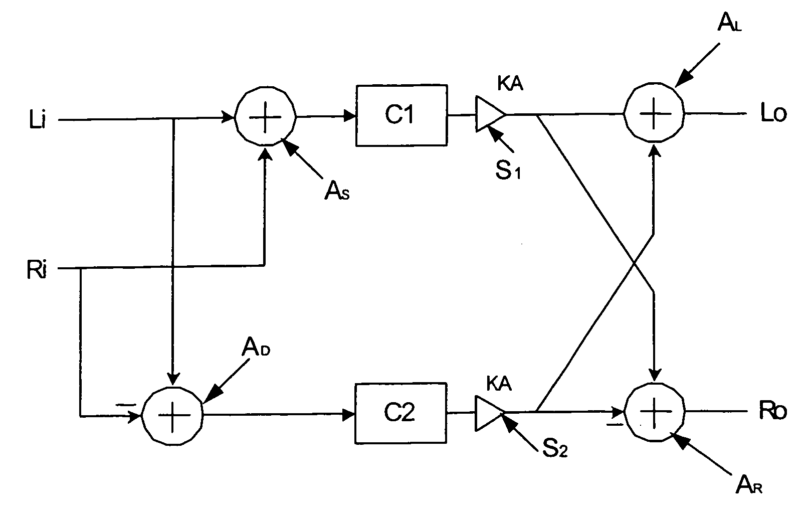
[0028]FIG. 4 shows an equaliser arrangement according to an embodiment. The equaliser has two inputs for receiving a left channel signal Li and a right channel signal Ri. The two input signal paths Li and Ri are coupled to an adder AS which sums the input signals to provide a sum signal (Li+Ri). These are then applied to a first or sum filter C1, and then to a scaling unit S1 which has a gain value of KA. When KA=0.5 it halves the amplitude of the signal output from the first filter C1. The two input paths Li and Ri are also coupled to a subtractor AD which provides a difference signal (Li−Ri) to a second filter C2. The output of the second filter C2 is coupled to a second scaling unit S2 also having a gain of KA, say 0.5. A second adder AL adds the processed difference signal from S2 (KA.C2.(Li−Ri)) to the processed sum signal from S1 (KA.C1.(Li+Ri)) to provide a left channel output signal Lo. A second subtractor AR subtracts the processed difference signal from S2 from the process...


PUM


Abstract

The present invention relates to audio signal processing such as equalisation and spatial enhancement functions. The present invention provides an audio signal processing circuit arrangement for two audio channels, and which combines spatial enhancement or acoustic mixing (crosstalk) cancelling with graphic equalisation functions. This is achieved with a circuit structure having a reduced filter count compared with known cascaded circuits dedicated to each function. The circuit structure processes the sum and difference signals through separate filters and then recombines them to recover the separate channels (adding and subtracting respectively).

Description

FIELD OF THE INVENTION [0001] The present invention relates to audio signal processing such as equalisation and spatial enhancement functions, and is particularly but not exclusively concerned with digital signal processing of digital audio signals. BACKGROUND OF THE INVENTION [0002] Two common effects for improving the perceived quality of stereo audio are stereo enhancement and frequency-response equalisation. [0003] Spatial or stereo enhancement effects work by cancelling crosstalk components that occur due to acoustic mixing of left and right signals between the loudspeaker and the ear. The result is to give an impression of increased stereo separation between channels. FIG. 1 shows how the listener's left ear (Le) receives signals intended for the right ear via path B, i.e. Le=A.Lo+B.Ro where Lo and Ro are the output signals from the left and right speakers and A and B are the acoustic transfer functions for paths A and B, and similarly, the right ear receives signals intended ...

Claims


Application Information

Patent Timeline
20 Apr 2006
Publication
US20060083381A1
IPC
H04R5/00; H04S1/00
CPC
H04S1/002; H04S1/00
Inventors
MAGRATH, ANTHONY J.