Electromedical implant

a technology of electromedical implants and electrodes, applied in the field of electromedical implants, can solve the problems of inability to achieve a cost effective bottom-up design, require considerable manual effort, and manufacture of electromedical implants in side-by-side construction, and achieve the effect of preventing faulty or incorrect installation of power supply units, ensuring safety, and ensuring safety

Inactive Publication Date: 2006-04-20
BIOTRONIX CRM PATENT AG
View PDF15 Cites 2 Cited by
  • Summary
  • Abstract
  • Description
  • Claims
  • Application Information

AI Technical Summary

Benefits of technology

[0016] Certain embodiments of the present invention avoid the above-mentioned disadvantages and provide an electromedical implant with a power supply unit that may be produced in the economical bottom-up design. The electromedical implant comprises a housing that is hermetically sealed off to the outside, and an advantageous power supply unit comprising a first shell with a first electrically conductive main surface and a first side wall, and a second shell comprising a second main surface and a second side wall. The power supply unit is embedded in the housing that is hermetically sealed off to the outside. An e

Problems solved by technology

Optimal space-saving utilization of space in the limited space available within the housing of such an implant is the big challenge that presents itself in an electromedical implant.
This design is associated with a serious disadvantage in that the manufacture of an electromedical implant in side-by-side construction so as to meet the above-mentioned requirements concerning utilization of space requires very considerable manual effort.
Unfortunately the capacity of power supply units is related to their volume, and for this reason the power supply unit will for an unforeseeable time remain the largest component of an electromedical implant, and therefore will remain the lowermost c

Method used


Image

  • Electromedical implant
  • Electromedical implant
  • Electromedical implant

Examples


Embodiment Construction

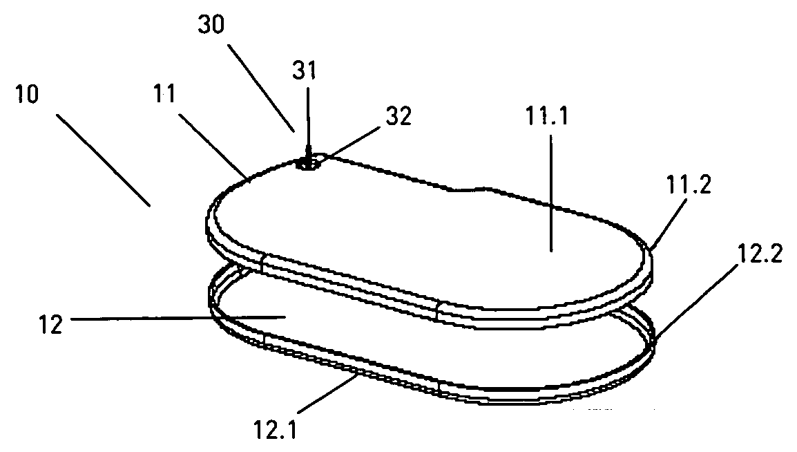
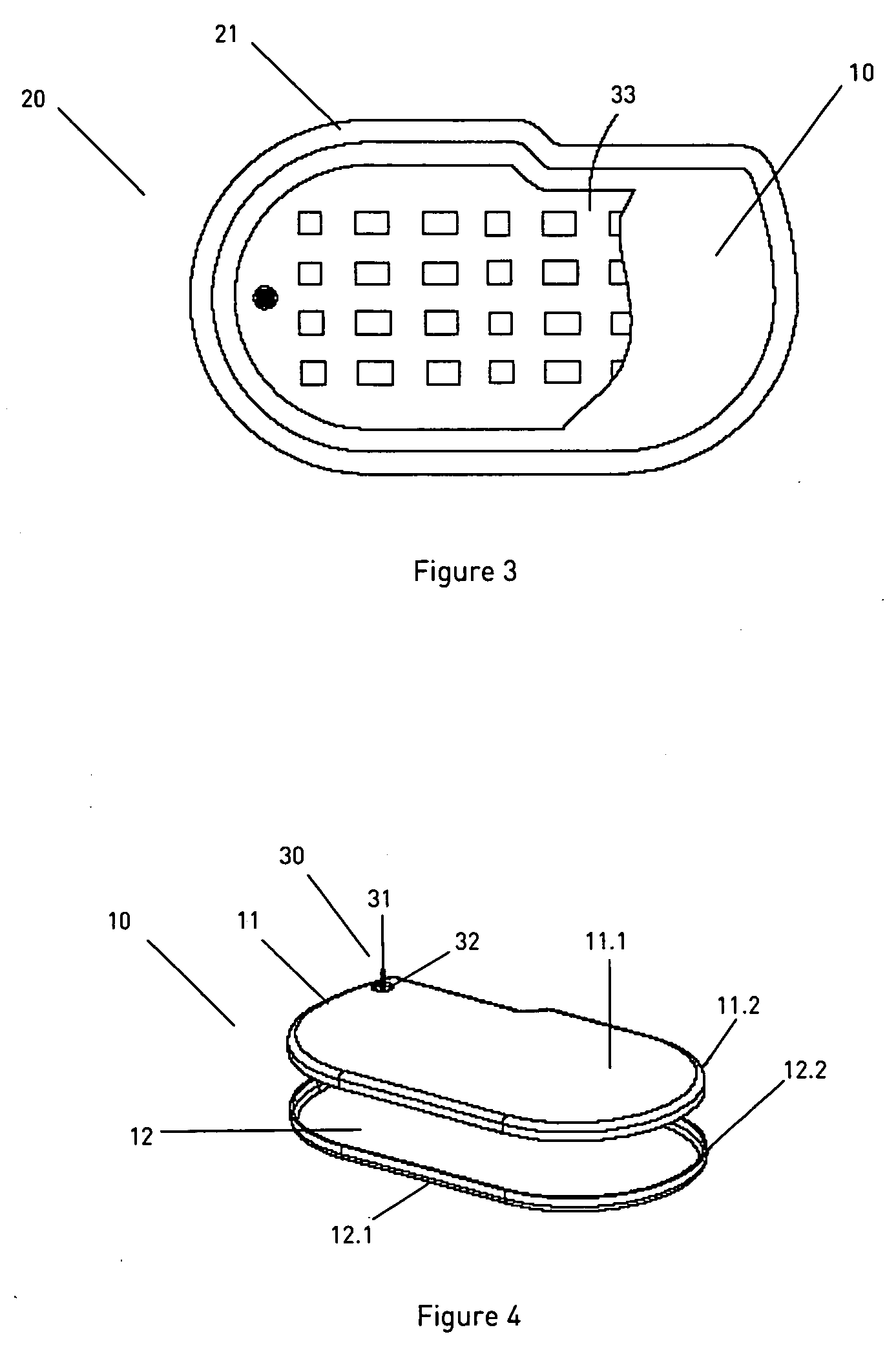
[0035]FIG. 3 shows the installed state of an electromedical implant 20. The housing 21, which is hermetically sealed off to the outside, the power supply unit 10 and the electrical control unit 33, which is installed on the first main surface 11.1 of the power supply unit, are shown. The first main surface 11.1 is designed such that it can accommodate the electrical control unit 33 of the implantable device 20. The size relationship between the base surface of the housing 21 that is hermetically sealed off to the outside and of the second main surface 12.1 of the power supply unit 10 is particularly favorable. In this arrangement the second main surface 12.1 of the power supply unit 10 has at least 0.7 times the surface of the base surface of the housing 21 of the electromedical implant 20. The following is favorable: 0.7 to 0.99 times the area, preferably 0.7 times to 0.95 times, particularly favorably 0.8 times to 0.9 times and particularly preferably 0.8 times to 0.85 times the s...


PUM


Abstract

An electromedical implant is disclosed comprising a housing which is hermetically sealed off to the outside; a power supply unit comprising a first shell with a first electrically conductive main surface and a first side wall, and a second shell comprising a second main surface and a second side wall which is embedded into the housing that is hermetically sealed off to the outside; a control unit that is electrically connected to the power supply unit; a header for contacting electrode lines, feedthroughs for leading away therapeutic pulses or pulse sequences from the housing that is hermetically sealed off to the outside. In this embodiment the electrical control unit is electrically connected to the power supply unit in a two-pole arrangement; the second main surface of the power supply unit has at least 0.7 times the surface of the base surface of the housing of the electromedical implant, which housing is hermetically sealed off to the outside; and the height of the power supply unit is at most 0.5 times the height of the housing of the electromedical implant, which housing is hermetically sealed off to the outside.

Description

CROSS-REFERENCE TO RELATED APPLICATIONS / INCORPORATION BY REFERENCE [0001] This U.S. patent application claims priority to and claims the benefit of the following German patent applications: [0002] DE 10 2004 049 778.8, filed Oct. 12, 2004; [0003] DE 10 2004 059 096.6, filed Dec. 6, 2004; and [0004] DE 10 2005 018 128.7, filed Apr. 20, 2005. TECHNICAL FIELD [0005] Certain embodiments of the present invention relate to electromedical implants. More particularly, certain embodiments of the present invention relate to an electromedical implant with a power supply unit for easy and economical production. BACKGROUND OF THE INVENTION [0006] Intercardiac therapy has developed into a standard procedure that has proven itself millions of times. In this process an electromedical implant is implanted in a skin pocket of a patient undergoing therapy, and is for example permanently electrically connected to the heart by way of an electrode line. Such electromedical implants include cardiac pacema...

Claims


Application Information

Patent Timeline
IPC IPC(8): A61N1/375H01M50/627
CPCA61N1/375A61N1/378H01M2/0202H01M2/065H01M2/361H01M10/052Y02E60/10H01M50/186H01M50/191H01M50/627
Inventor DREWS, JURGENHICKMANN, STEFFENFEHRMANN, DIPL-CHEM GERDNEUMANN, WIEBKESTAUB, ROLANDUHRLANDT, WERNER
Owner BIOTRONIX CRM PATENT AG
Why Eureka
Try Eureka