
Method and apparatus for modeling and analyzing light

Inactive Publication Date: 2006-04-20
LIGHT FOUNDRY
View PDF0 Cites 19 Cited by
  • Summary
  • Abstract
  • Description
  • Claims
  • Application Information

AI Technical Summary

Benefits of technology

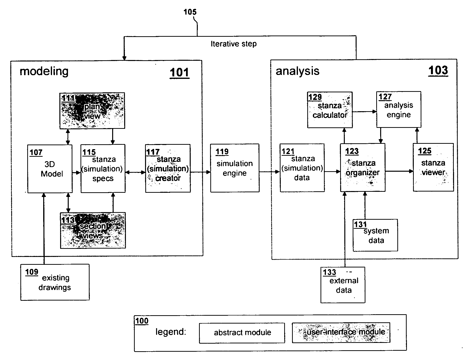
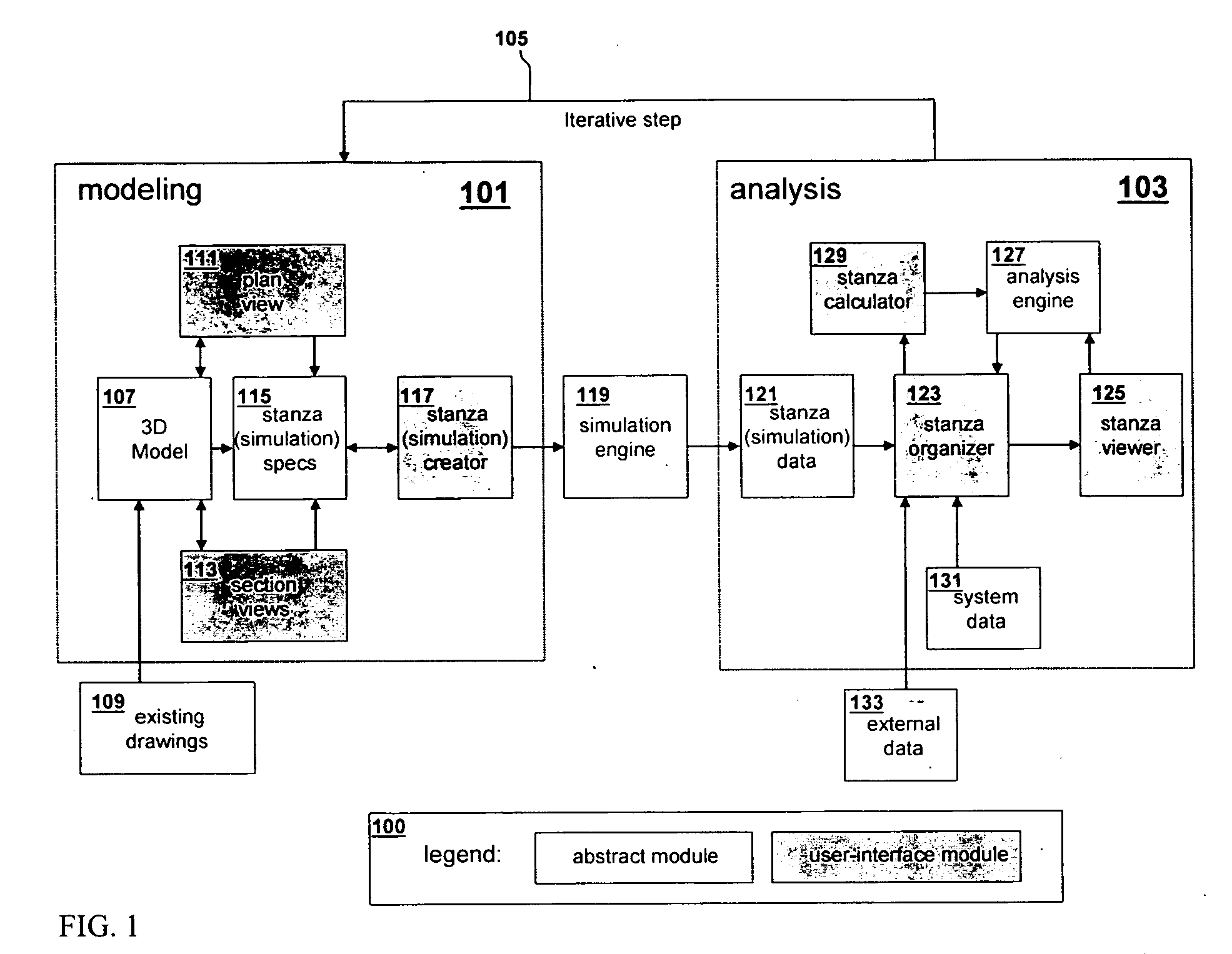
[0011] The objects and advantages of this invention allow a person to quickly iterate through a number of modeling and analysis cycles to optimize lighting performance. Rapid modeling is achieved through stroke interpretation, drawing layers, and plan / section representation of 3D models. The analysis is simplified through an organizer that manages many design iterations, provides an infrastructure for comparing and manipulating results graphically, as well as a visualization tool. Architectural Pens

Problems solved by technology

However, a major obstacle to this is that lighting simulation is a complex multidimensional problem with site (e.g., orientation, latitude, season), design (e.g., shape of building, window glazing, lamps), and occupancy (schedules, controls, visual quality) variables that existing products and tools do not manage well.
At the other extreme are tools that model major variables of light, but are extremely cumbersome and inappropriate for iterative design.
Hence, although lighting is consistently identified as a critical variable in building design, there are few comprehensive and usable tools for the average architect, engineer, and designer to model and analyze light.
Physical models built to scale are easy to construct with materials like chipboard and glue, but are limited in analysis power, cumbersome to transport, and can be costly in terms of time and materials.
Calibrated tables and sky chambers correct for some analysis shortcomings, but are expensive and still require tedious manual operation to get information from sensors or cameras.
Further, there are no practical ways of scaling electric lighting components which are crucial components of a lighting system.
Hence, although physical models are familiar to architects, they are largely impractical as analysis tools and have limited impact on the design profession today.
Omitting windows, skylights, and other natural light sources simplified these calculations, at a cost of analysis accuracy.
As described in the limitations of modelers in '279, these types of modelers are too complex for a typical professional and require intensive training sessions to learn.
Further, the perspective drawings produced by this camera foreshorten lengths and angles making it difficult to see true length without measuring tools.
These results are presented individually or in tabular format, yet cannot be mechanically compared, simplified, or managed in any way.
Scale differences aside, peaks in each cell can be identified and roughly compared, but other aspects such as finding the highest average, the number of days meeting a lighting requirement, or the best January performance is difficult to ascertain from this static representation of multiple variables.
Generic spreadsheets with data in row and columns are ill-suited for storing, viewing, and analyzing architectural lighting data which varies by two or three spatial axes as well as time of day and season.
2D data subsets can be managed, but this is at a cost of missing important trends in the data.
Scripting languages and mathematical packages allow symbolic manipulation of information, but require significant programming or engineering skills that are inappropriate for most people in the building industry.
All these cases are further complicated since they require the user to export data from their lighting simulation program into these tools, further slowing the iterative design process.
In summary, architects, engineers, and designers do not have access to rapid modeling and analysis tools for exploring the full dimensionality of light.
Existing modeling tools are either but cumbersome, or quick and of limited use.
Analysis tools do not provide support for making sense of the rich, multidimensional data that is produced through simulation.
Combined, these limitations make it difficult to iterate and test a number of design scenarios to optimize lighting quality for a building.

Method used


Image

  • Method and apparatus for modeling and analyzing light
  • Method and apparatus for modeling and analyzing light
  • Method and apparatus for modeling and analyzing light

Examples


Embodiment Construction

[0049] The objects and advantages of this invention allow a person to quickly iterate through a number of modeling and analysis cycles to optimize lighting performance. Rapid modeling is achieved through stroke interpretation, drawing layers, and plan / section representation of 3D models. The analysis is simplified through an organizer that manages many design iterations, provides an infrastructure for comparing and manipulating results graphically, as well as a visualization tool.

Architectural Pens

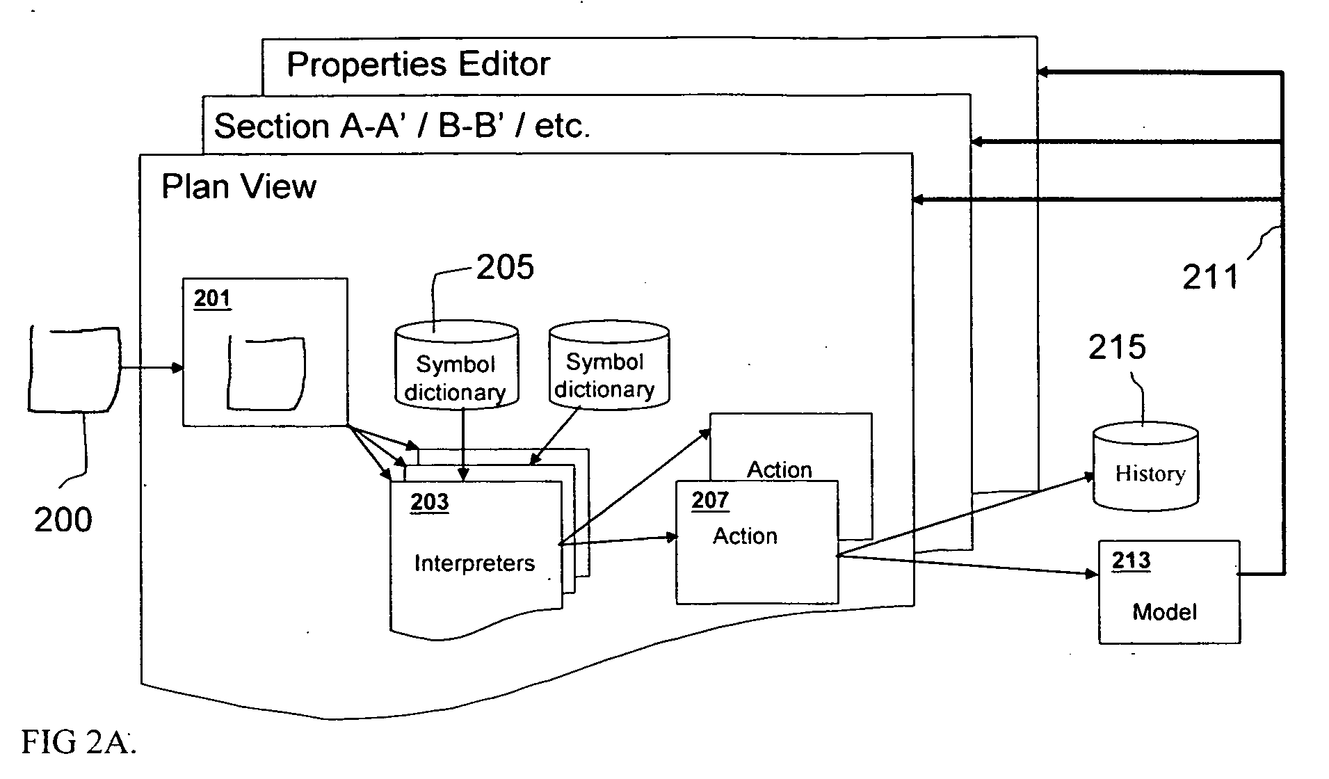
[0050] The user is allowed to choose pens that have specific behavior for creating different types of architectural geometry. Just as there are pens with different attributes for writers and illustrators, architects need pens that can draw different types of basic geometry. The “ortho” pen, for example, allows the user to draw lines that are only horizontal or vertical. With existing CAD tools, a special command, mask, or designation is invoked when drawing a line stay on axis.

Glypths...


PUM


Abstract

Described is a modeling and analysis design environment allowing the specification of an architectural lighting system, composed of both natural and artificial lighting elements and lighting controls. The modeling environment allows users to create 3D models through a series of plan and section drawings. Its glyph language also provides for quick specification of elements such as windows, luminaires, and control systems. The analysis workbench provides both visual and robust way of analyzing multidimensional data, characteristic of lighting simulation. One aspect of the invention is a method for evaluating combinations of artificial and natural lighting to optimize lighting quality and energy cost. This method includes using integrated Plan / Section approach for specification of 3D lighting models, glyph language for quick specification of geometry in Plan / Section, a calculation manager, and visual, spreadsheet-like language for managing spatial and temporal data.

Description

CLAIM OF PRIORITY [0001] This application claims the benefit of priority to U.S. Provisional Application Ser. No. 60 / 600,887 filed Aug. 11, 2004, which is incorporated by reference herein.FIELD OF THE INVENTION [0002] This invention relates to three dimensional modeling and analysis of multidimensional data performance data. BACKGROUND OF THE INVENTION [0003] For over a century, architects, engineers, and designers have understood the importance of lighting simulation as offering a wealth of information about visual and environmental performance of a building before construction. Through simulation, they are able to avoid costly repairs, inefficient operations, and occupant discomfort. Instrumental to achieving a good building, professionals require quick, iterative design tools for their own analysis as well as for communication with others. However, a major obstacle to this is that lighting simulation is a complex multidimensional problem with site (e.g., orientation, latitude, se...

Claims


Application Information

Patent Timeline
IPC IPC(8): G06F17/50
CPCG06F17/5009G06F2217/86G06F30/20G06F2117/08
Inventor GLASER, DANIEL C.VOUNG, JANXIAO, LING
Owner LIGHT FOUNDRY
Learn More