Simulating ion impingement

a technology of ion impingement and simulation, which is applied in the direction of machines/engines, separation processes, instruments, etc., can solve the problems of limited performance of chemical thrusters in use today, relatively large ions, and loss of performance, so as to minimize spacecraft cross-section, reduce the amount of charge buildup, and dissipate the additional heat load of ion impingement

Inactive Publication Date: 2006-01-12
THE BOEING CO
View PDF3 Cites 11 Cited by
  • Summary
  • Abstract
  • Description
  • Claims
  • Application Information

AI Technical Summary

Benefits of technology

[0016] Another preferred embodiment of the invention optimizes variable parameters in flight to minimize ion impingement. The system exploits strategies that include turning off the thrusters, reducing the mass flow to the thrusters, or orienting the thrusters (e.g. by gimbals or by changing the spacecraft attitude) to reduce the fraction of ions that travel perpendicular to the magnetic field.
[0019] Another preferred embodiment inputs data about the spacecraft, its initial trajectory, and the ion thrust profile; automatically applies selected operational techniques above (e.g. turn off the thrusters) to the model when certain criteria are met (e.g. when ion impingement heating exceeds a user-specified rate); computes the effect of the applied techniques to estimate the resulting modified trajectory; and repeats the process by applying selected operational techniques at the next point along the modified trajectory where the selected criteria are met. This embodiment reports maximum rates and integrated totals for the ion effects. It allows the user to repeat an analysis after changing some or all of the criteria for applying various operational techniques; this allows rapid iteration of “what if” scenarios to optimize a mission design.
[0020] Another preferred embodiment incorporates the features above and is implemented as a plug-in module for a more comprehensive mission design tool such as Software Tool Kit (STK). This facilitates many-faceted mission optimization, including such criteria as total radiation exposure in the Earth's radiation belts, planetary shadowing that blocks sunlight to solar arrays, exposure to atomic oxygen, total time to complete a maneuver, and visibility of ground-based communication antennas.

Problems solved by technology

Chemical thrusters in use today are limited by how much energy is released during the combustion process.
One problem with the use of an ion thruster is damage and loss of performance due to impingement of ion plumes on spacecraft.
The problem arises from the effect of Earth's magnetic field on the ions that are ejected by an ion thruster.
Furthermore, thrusters used to date use xenon as propellant, so the ions are relatively massive.
One problem is lost thrust: the ions striking the spacecraft carry momentum and strike from the front, destroying 1% of the nominal thrust.
Dispelling heat is another problem: JIMO has about 100 kW of kinetic power in the ion beam, so the impinging ions add ˜1 kW of thermal load to the vehicle's radiators.
A third problem is erosion: if its ion thruster expels 1 metric ton of Xe getting from LEO to higher orbit, then JIMO catches around 10 kg of xenon ions at 64 kilometers per second.
If the ion impacts cause a comparable mass of material to be sputtered off, the spacecraft's coatings could be seriously degraded.
If some of the sputtered material collects on optics or other sensitive surfaces, mission performance could be compromised.
A fourth problem is charge deposition: 10 kg of xenon ions carry a total charge of 7.54 million coulombs.

Method used


Image

  • Simulating ion impingement
  • Simulating ion impingement
  • Simulating ion impingement

Examples


Embodiment Construction

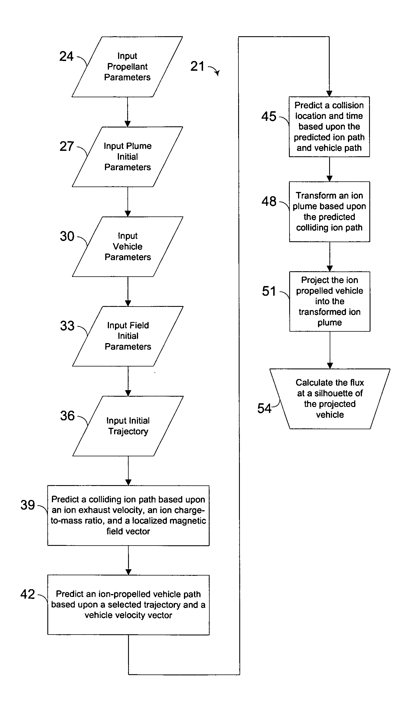
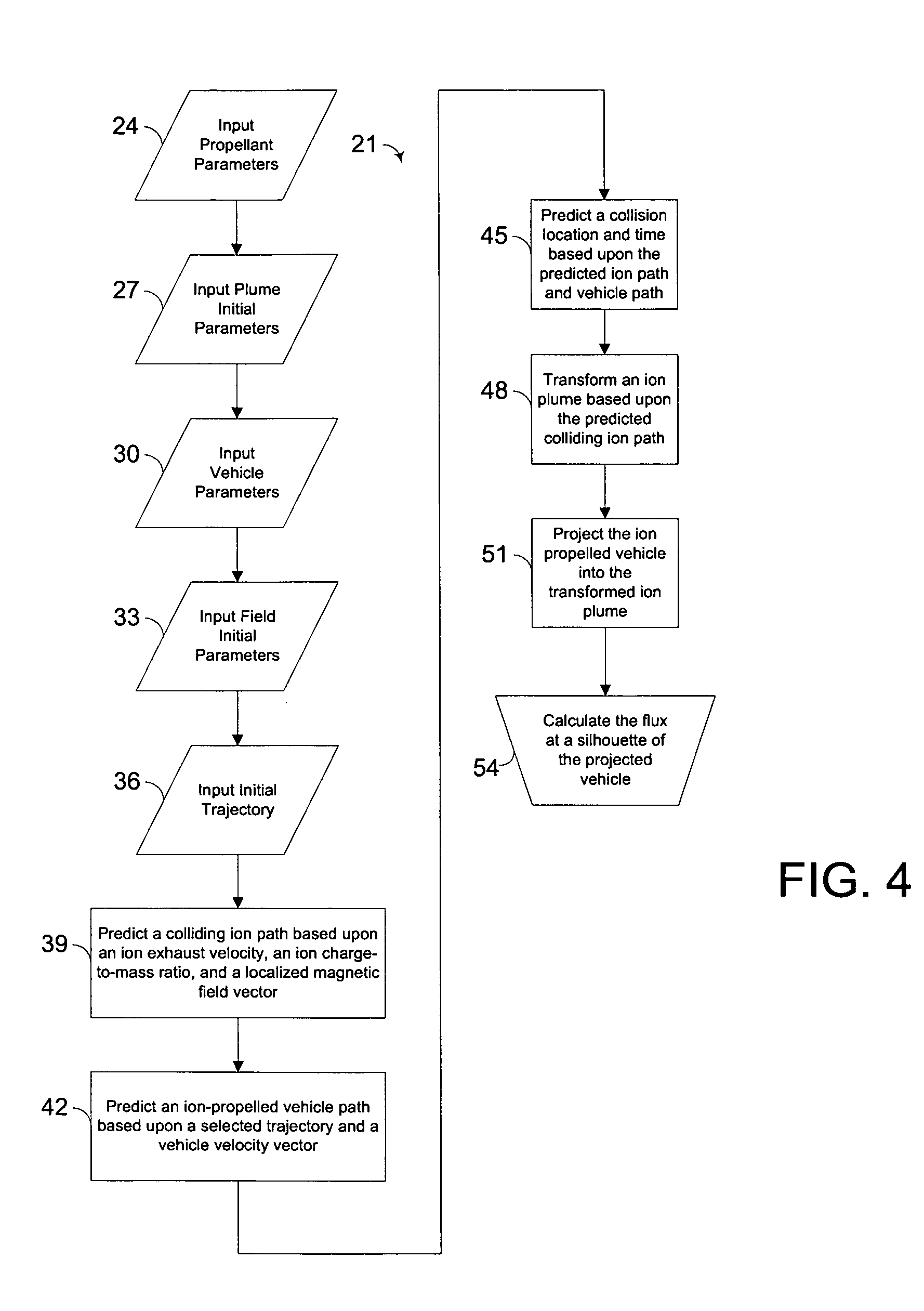
[0033] By way of overview, a method and a computer software program for predicting and modeling ion flux colliding with an ion-propelled vehicle traversing a magnetic field predicts a colliding ion path based upon an ion exhaust velocity, an ion charge-to-mass ratio, and a localized magnetic field vector. An ion-propelled vehicle path is predicted based upon a selected trajectory and a vehicle velocity vector. An ion plume is transformed based upon the predicted colliding ion path. The ion-propelled vehicle is projected into the transformed ion plume. The flux is calculated at a silhouette of the projected vehicle.

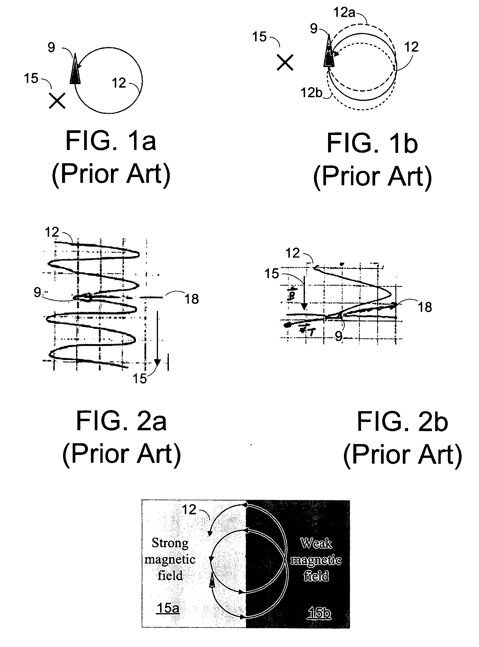
[0034] An important point is that although the ion beam diverges in two dimensions (i.e. azimuth and elevation relative to the beam axis), one dimension of divergence does not reduce the flux of ions returning to the spacecraft. Referring to FIG. 1a,

[0035] As indicated, one problem with the use of an ion thruster is damage and loss of performance due to impingement of io...


PUM


Abstract

A method and a computer software program for predicting and modeling ion flux colliding with an ion-propelled vehicle traversing a magnetic field predicts a colliding ion path based upon an ion exhaust velocity, an ion charge-to-mass ratio, and a localized magnetic field vector. An ion-propelled vehicle path is predicted based upon a selected trajectory and a vehicle velocity vector. An ion plume is transformed based upon the predicted colliding ion path. The ion-propelled vehicle is projected into the transformed ion plume. The flux is calculated at a silhouette of the projected vehicle.

Description

FIELD OF THE INVENTION [0001] This invention relates generally to ion thrusting technology and, more specifically, to ion impingement control. BACKGROUND OF THE INVENTION [0002]02 While most current satellites use a chemical bipropellant propulsion system, a XIPS-equipped satellite instead uses the impulse generated by a thruster ejecting electrically charged particles at high velocities. XIPS requires only one propellant, xenon, and does its stationkeeping job using a fraction of that required by a chemical propellant system. [0003] The heart of the XIPS is the ion thruster, measuring less than 10 inches across. Two other key units include a tank containing xenon gas and a power processor. Thrust is created by accelerating the positive ions through a series of gridded electrodes at one end of the thrust chamber. The electrodes, known as an ion extraction assembly, create more than 3,000 tiny beams of thrust. The beams are, to some extent, prevented from being electrically attracted...

Claims


Application Information

Patent Timeline
Patent Type & Authority Applications(United States)
IPC IPC(8): B01D59/44
CPCB64G1/242F03H1/00B64G1/405
Inventor TILLOTSON, BRIAN J.
Owner THE BOEING CO
Why Eureka
Try Eureka