Adjustable dual stage trigger mechanism for semi-automatic weapons

a dual-stage, automatic technology, applied in the direction of breech mechanism, small arms, ammunition loading, etc., can solve the problems of reducing the strength of hammers, the inability of the adjustment screw of sufficient diameter to bear directly on the disconnector spring to be fitted to the disconnector in the space, and the difficulty of both adjustment screws on one end of the disconnector, etc., to reduce the hammer strength, reduce the hammer mass, and eliminate the damage to the screw threads

Active Publication Date: 2006-04-27
WHG PROPERTIES
View PDF3 Cites 41 Cited by
  • Summary
  • Abstract
  • Description
  • Claims
  • Application Information

AI Technical Summary

Benefits of technology

[0006] The instant invention also presents an improvement over Milazzo's disconnector adjustment screw by threadedly engaging the adjustment screw into the disconnector rather than the trigger and allowing the head of the screw to act as a stop against the trigger by the use of a tower that extends over the disconnector. The subtended area of the head of the present invention's adjustment screw is larger than the area subtended by the end of the threaded shank of the screw. The larger area resists the battering force of the pivoting disconnector and damage to the screw threads is eliminated as the screw is supported by a sufficient length of thread engagement into the disconnector.
[0007] A further improvement of the present invention is a lightweight yet strong hammer that allows the hammer to rotate faster under the force of the hammer spring than a standard hammer. It is well known in the art that hammer mass may be reduced by drilling holes or making apertures in firearm hammers but this method reduces the hammers strength. The hammer of the instant invention reduces hammer mass by incorporating an “I-beam” shape to the hammer. It is well known that one of the lightest, yet strong and stiff structural members is an I-beam as the I-beam concept of a thin centrally located web with extending flanges at the ends of the web makes very efficient use of the structural member's material. The hammer of the present invention uses the I-beam concept to reduce hammer mass while retaining hammer strength so that the hammer can withstand the repeated impact imparted to the hammer body during the firing cycle while still being lightweight.

Problems solved by technology

Due to space constraints placing both adjustment screws on one end of the disconnector is difficult.
An adjustment screw of sufficient diameter that will bear directly on the disconnector spring cannot be fitted to the disconnector in the space available in the lower receiver on most AR15 rifles.
It is well known in the art that hammer mass may be reduced by drilling holes or making apertures in firearm hammers but this method reduces the hammers strength.

Method used


Image

  • Adjustable dual stage trigger mechanism for semi-automatic weapons
  • Adjustable dual stage trigger mechanism for semi-automatic weapons
  • Adjustable dual stage trigger mechanism for semi-automatic weapons

Examples


Embodiment Construction

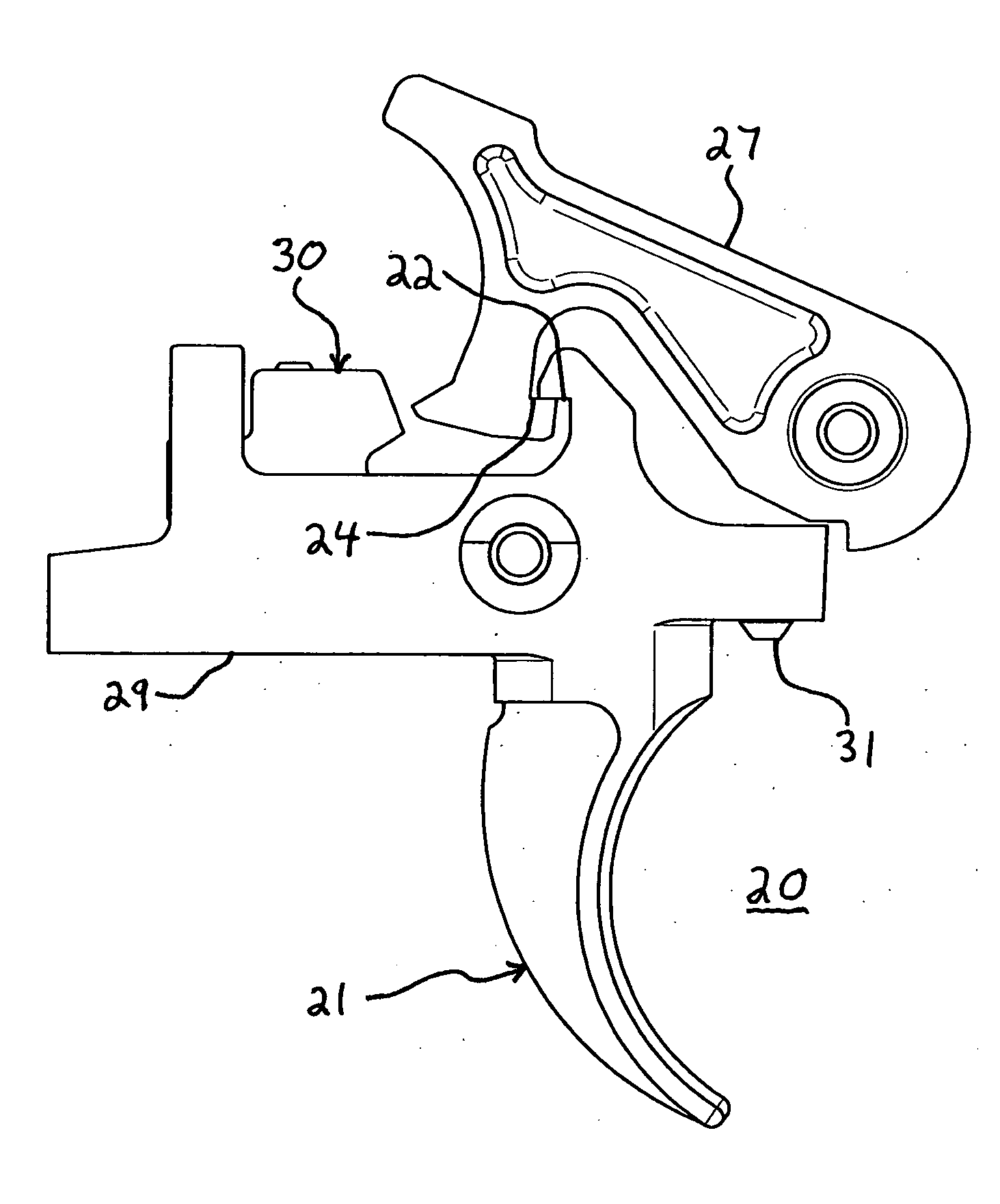
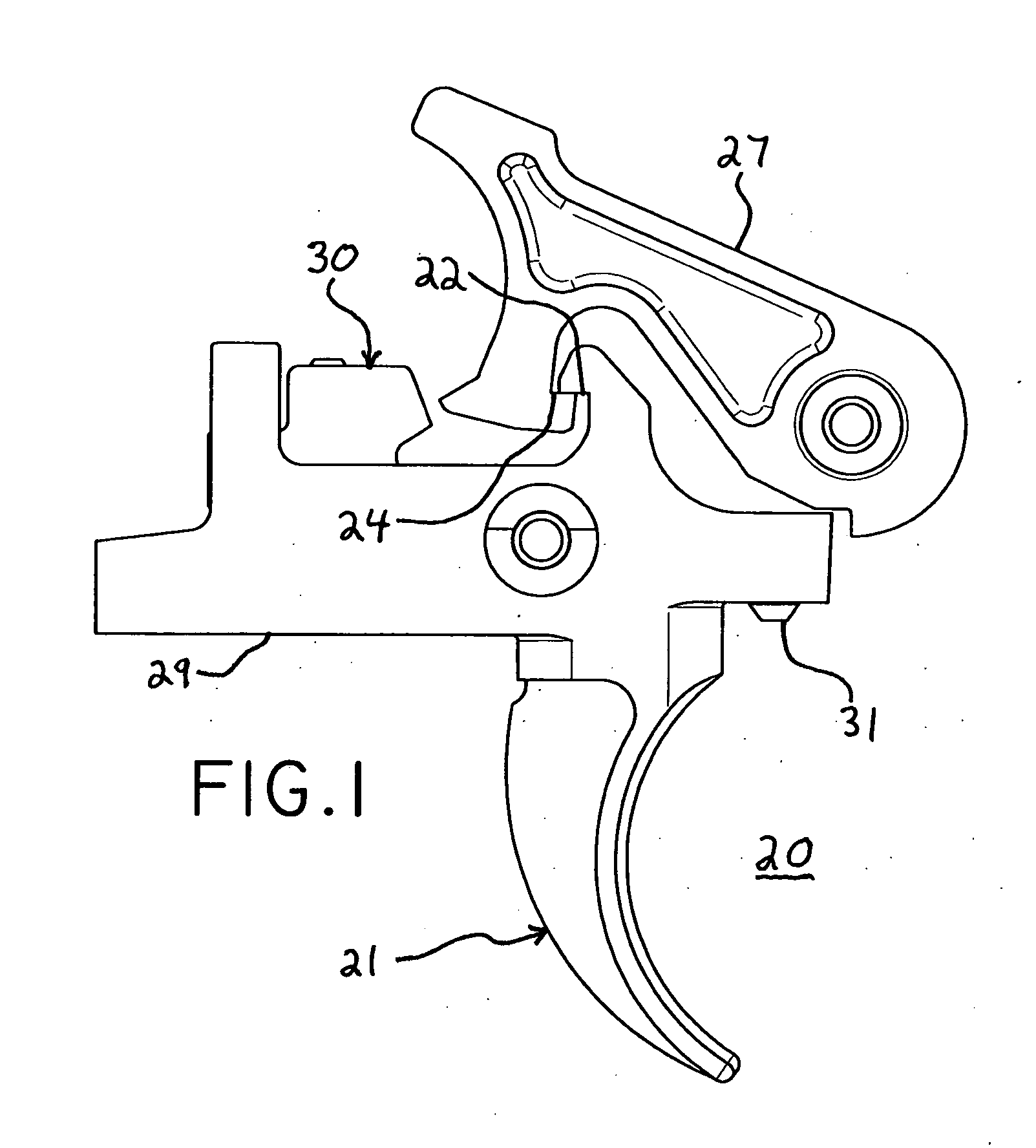
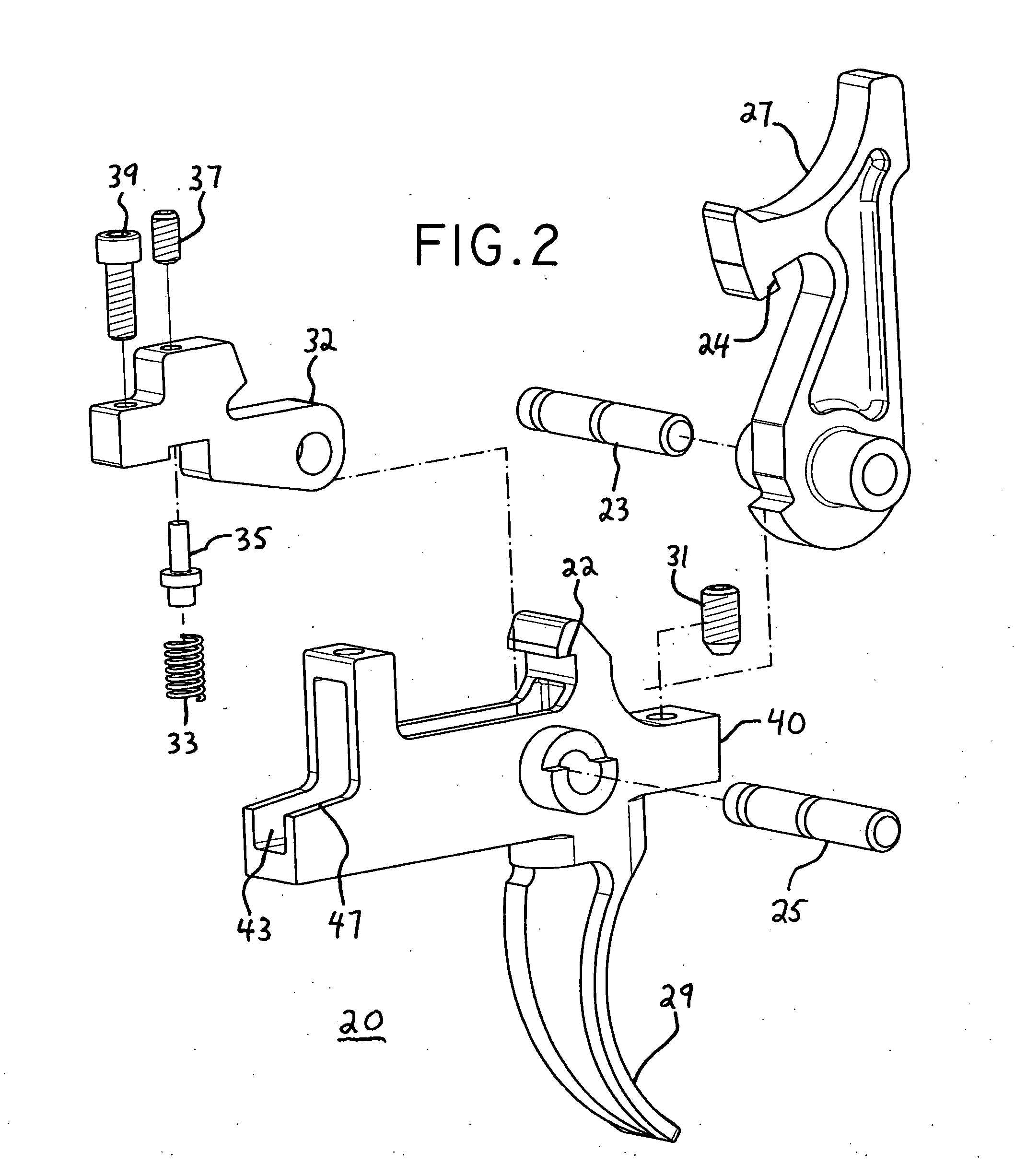
[0023] The present invention is now described in conjunction with the drawings in which like reference characters indicate corresponding elements throughout the several views. Attention is first directed to FIG. 1 which illustrates the trigger mechanism, generally designated 20 and FIG. 2 which is an exploded view of the trigger mechanism 20 of FIG. 1. It will be understood that trigger mechanism 20 is intended to be employed with any of the various M16 type firearms; however with minor modifications it could be more widely used for other firearms as well. M16 type firearms include the AR15 family of rifles, the M4 carbine family of rifles, the SR25 and AR10 larger caliber type M16 rifles and other rifles that use the AR15 trigger assembly. It will also be understood that trigger mechanism 20 is carried by a lower receiver of a firearm. A lower receiver is not shown, as they are well known in the art and trigger mechanism 20 is carried in the conventional manner using cross pins 23 ...


PUM


Abstract

A dual stage trigger assembly for a firearm. The trigger assembly comprises a spring loaded lightweight hammer, a spring loaded trigger, a spring loaded disconnector, a spring follower for the disconnector spring and two adjustment screws that allow the user the ability to adjust the sear face of the trigger that is engaged with the hammer in the cocked position and adjust the force imparted to the disconnector by the disconnector spring.

Description

RELATED APPLICATIONS [0001] This application claims benefit of Provisional Patent Application Ser. No.: 60 / 621,133, filed 22 Oct. 2004, titled: Adjustable Dual Stage Trigger Mechanism for Semi-Automatic Weapons.FIELD OF INVENTION [0002] This invention pertains to trigger mechanisms for fire arms and more particularly to a dual stage trigger mechanism for semi-automatic weapons. BACKGROUND OF THE INVENTION [0003] This invention relates to trigger mechanisms for semi-automatic firearms. Particularly, the invention relates to trigger mechanisms for the AR15 and M16 type rifles but with modifications may be used in other firearms. Related prior art is U.S. Pat. No. 6,131,324 issued Oct. 17, 2000 to Jewell, and U.S. Pat. No. 5,501,134 issued Mar. 26, 1996 to Milazzo. Jewell discloses a dual stage trigger assembly that allows user adjustability of sear engagement and disconnector spring force. A disconnector in Jewell is double ended with two distinct ends across the disconnector pivot po...

Claims


Application Information

Patent Timeline
Patent Type & Authority Applications(United States)
IPC IPC(8): F41A3/00
CPCF41A19/16F41A19/44
Inventor GEISSELE, WILLIAM HUGO
Owner WHG PROPERTIES
Why Eureka
Try Eureka