
Radar system using quadrature signal

a quadrature signal and radar technology, applied in the direction of oscillator generators, instruments, measurement devices, etc., can solve the problems of increasing manufacturing costs, requiring high-performance devices, and difficult signals in such frequency bands, so as to prevent the increase in the noise figure of the receiving end caused by the leakage power of the sending end, increase the receiving sensitivity, and prevent the effect of leakage signal saturation on the receiver

Active Publication Date: 2006-04-27
SAMSUNG ELECTRONICS CO LTD
View PDF9 Cites 22 Cited by
  • Summary
  • Abstract
  • Description
  • Claims
  • Application Information

AI Technical Summary

Benefits of technology

[0014] It is, therefore, an object of the present invention to provide a low-price, high-sensitivity subminiature radar system. It is another object to provide a quadrature push-push oscillator composed of low frequency elements to offset a leakage signal of a sending end and thus, increase receiving sensitivity. It is another object of the invention wherein the saturation on the receiver caused by the leakage signal of the sending end can be prevented. It is yet another object of the invention wherein the increase in the noise figure of the receiving end caused by the leakage power of the sending end is prevented. It is yet a further object of the invention in which the size of the radar system can be markedly reduced by sharing a transmitting and receiving antenna.
[0015] Another object of the present invention is to provide a low-price, high-performance radar system, in which a quadrature subharmonic mixer for the receiving end is used to suppress the occurrence of a DC-offset, that results from the even order distortion due to jamming and self-mixing of a mixer due to signal leakage of a local oscillator; and the directional information on a target object, e.g., whether the target object is getting closer or farther away, can be obtained.
[0016] Still another object of the present invention is to provide an adaptive radar system featuring a high isolation between the sending and receiving ends by monitoring output values of a mixer and correcting a mismatch of quadrature push-push signals through a DSP (Digital Signal Processor).

Problems solved by technology

However, making a signal source in such frequency band is very difficult and requires high-performance devices, which in turn increases costs of manufacture.
Thus, if a signal flows from a sending end with high power output into a receiving end, the receiving sensitivity of the radar system becomes so low that the radar system cannot detect a weak received signal.
In addition, if a high power signal flows into the receiving end, then a low noise amplifier 105 or a mixer 106 of the receiving end may become saturated, thereby deteriorating the entire system characteristics.
Also, because of the leakage signal of the sending end the noise figure of the receiving end gets worse.
Nevertheless, these advantages do not necessarily outweigh the problem caused by using two antennas 104.
Moreover, in case of a Doppler radar, the Doppler shift is extremely low between tens of Hz to hundreds of kHz, so the radar is under heavy influence of flicker noise and therefore the receiving sensitivity of the radar is markedly deteriorated.

Method used


Image

  • Radar system using quadrature signal
  • Radar system using quadrature signal
  • Radar system using quadrature signal

Examples


Embodiment Construction

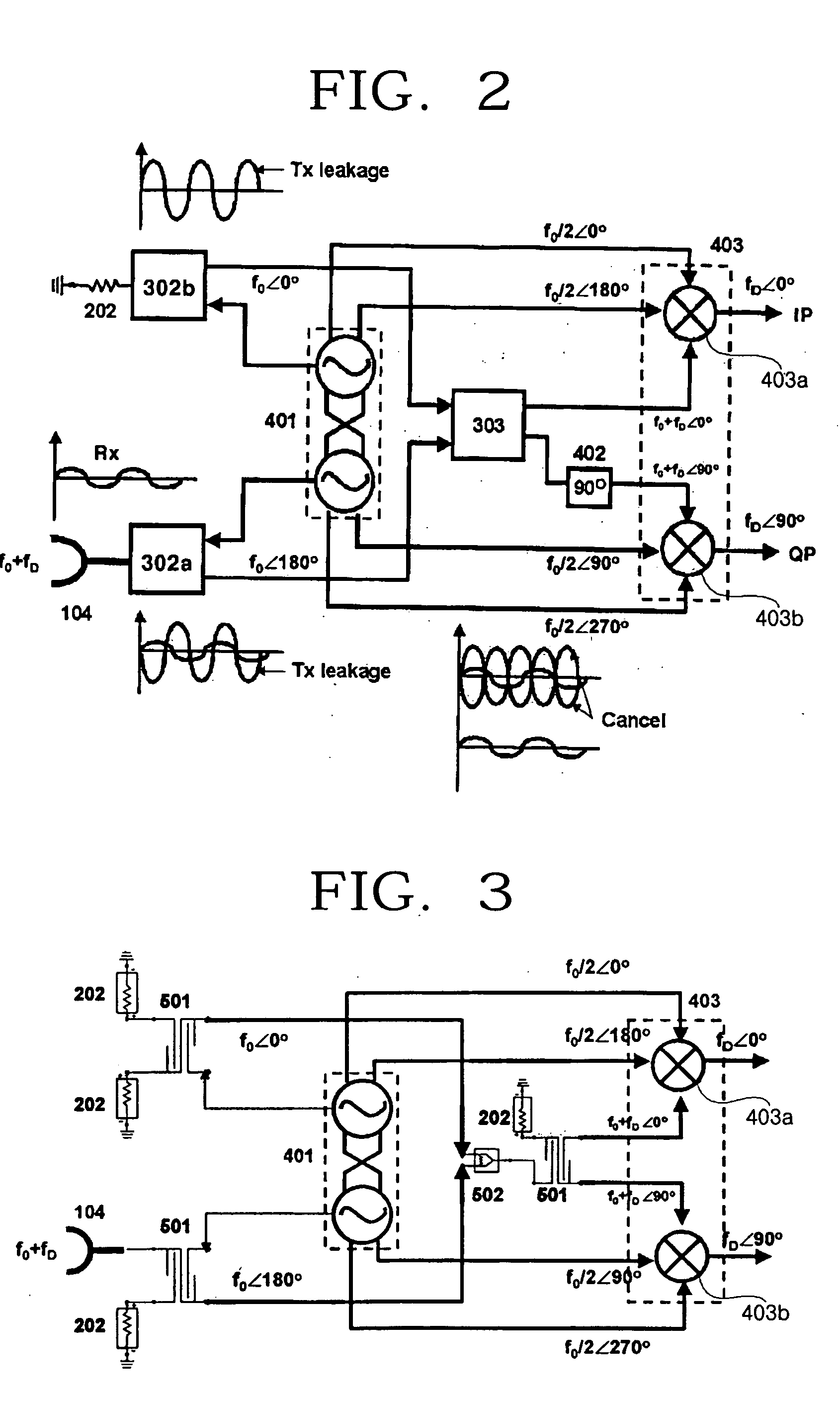
[0033] Preferred embodiments of the present invention will be described herein below with reference to the accompanying drawings.

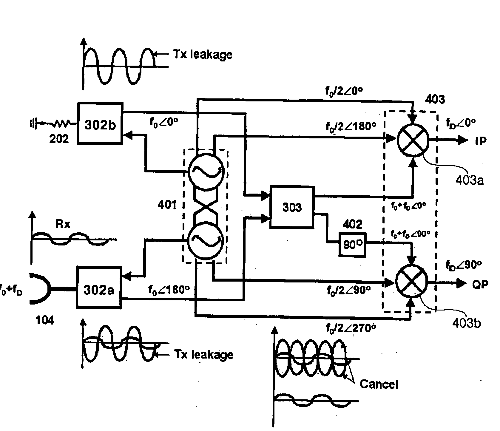
[0034]FIG. 2 is a circuit diagram of a radar system according to one exemplary embodiment of the present invention. Referring to FIG. 2, the radar system of the present invention includes a quadrature push-push oscillator 401, a first coupler block 302a, a second coupler block 302b, a power combiner 303, a 90-degree phase shifter 402, and a quadrature subharmonic mixer 403. The quadrature subharmonic mixture 403 includes a first quadrature mixer 403a and a second quadrature mixer 403b.

[0035] The quadrature push-push oscillator 401 generates four harmonics with a 90-degree phase difference between them, and produces two-balanced 2nd harmonic signals therefrom.

[0036] The first coupler block 302a radiates through the antenna 104 one of the 2nd harmonic signals produced by the quadrature push-push oscillator 401, and the second coupler block 303b terminates...


PUM


Abstract

A radar system using a quadrature signal includes a quadrature push-push oscillator for generating four harmonics with a 90-degree phase difference from each other, and producing two-balanced 2nd harmonic signals from the harmonics; a first coupler block for radiating one of the 2nd harmonics through an antenna; a second coupler block for terminating the other 2nd harmonic to ground; and a power combiner for combining a transmitted signal that is leaked from the first and second coupler blocks with the received signal that is radiated through the antenna. The radar system features an improved receiving sensitivity by offsetting the leakage signals of the sending end. Also, the radar system can be made very small by using a single antenna for transmitting and receiving.

Description

CROSS-REFERENCE TO RELATED APPLICATIONS [0001] This application claims benefit under 35 U.S.C. § 119 from Korean Patent Application No. 10-2004-0054442, filed on Jul. 13, 2004, the entire content of which is incorporated herein by reference. BACKGROUND OF THE INVENTION [0002] 1. Field of the Invention [0003] The present invention relates in general to a radar system using a quadrature signal. More specifically, an exemplary embodiment of the present invention relates to a low-price, high-sensitivity, high-performance subminiature radar system using a quadrature signal, wherein the radar system has many advantages in that a quadrature push-push oscillator composed of low frequency elements is employed to offset a leakage signal of a sending end and thus, increases receiving sensitivity; an increase in a noise figure of a receiving end caused by the leakage power can be prevented; the size of the radar system can be reduced markedly by sharing a transmitting and receiving antenna; a q...

Claims


Application Information

Patent Timeline
Patent Type & Authority Applications(United States)
IPC IPC(8): G01S7/35
CPCG01S7/032H03B27/00H03B2200/0078H03B5/1228H03B2200/007H03B5/1221G01S13/34
Inventor SONG, IN-SANGHONG, SONG-CHEOLKO, SANG-SOOKIM, JEONG-GEUNKIM, HONG-CHAN
Owner SAMSUNG ELECTRONICS CO LTD
Learn More