Thrust needle roller bearing

a needle roller bearing and thrust technology, applied in the direction of rolling contact bearings, shafts and bearings, rotary bearings, etc., can solve the problems of increasing manufacturing costs, unsuitable for the majority variety/minority lot production required to satisfy a recent trend of diversification of needs, etc., to reduce differential slippage of needle rollers, improve durability, and improve the effect of processing cos

Inactive Publication Date: 2006-04-27
NTN CORP
View PDF7 Cites 14 Cited by
  • Summary
  • Abstract
  • Description
  • Claims
  • Application Information

AI Technical Summary

Benefits of technology

[0012] It is, therefore, an object of the present invention to provide a double row thrust needle roller bearing which can suppress the differential slippage of...

Problems solved by technology

While the double row thrust needle roller bearing of the prior art has the above mentioned advantages and is suitable for the minority variety/majority lot production, it is not suitable for the majority variety/mino...

Method used


Image

  • Thrust needle roller bearing
  • Thrust needle roller bearing
  • Thrust needle roller bearing

Examples


first embodiment

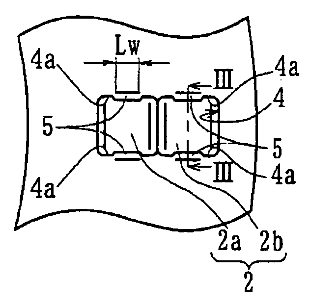
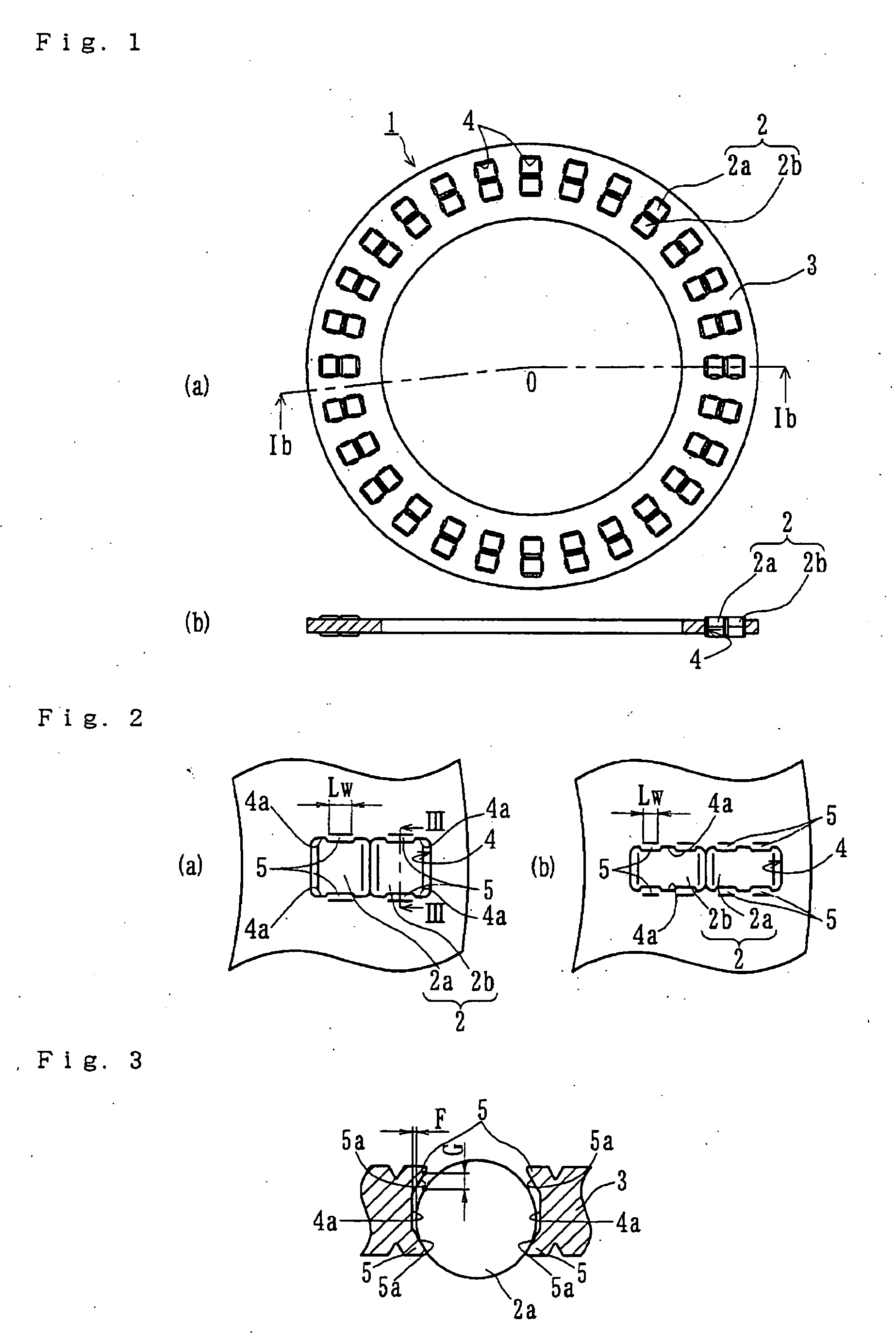
[0048]FIG. 1(a) is a plan view of a double row thrust needle roller bearing of the present invention. FIG. 1(b) is a cross-sectional view taken along a line Ib-O-Ib in FIG. 1(a). FIG. 2(a) is a partial enlarged view of FIG. 1(a). FIG. 2(b) is a similar partial enlarged view of a modified embodiment of FIG. 2(a). FIG. 3 is a cross-sectional view taken along a line III-III in FIG. 2(a).

[0049] The double row thrust needle roller bearing 1 includes a plurality of needle rollers 2, and a cage 3 to hold the needle rollers 2 at a predetermined pitch in the circumferential direction. The cage 3 is made by cutting soft metal materials such as copper alloy; some examples are high tensile brass casting (JIS CAC 3 etc.), aluminum / bronze casting (JIS CAC 7 etc.), aluminum, aluminum alloy, or aluminum alloy casting. The cage 3 has a plurality of pockets 4 each formed as a rectangular configuration. Each pocket 4 has a length of its longitudinal (radial) side longer than that of each needle roller...

second embodiment

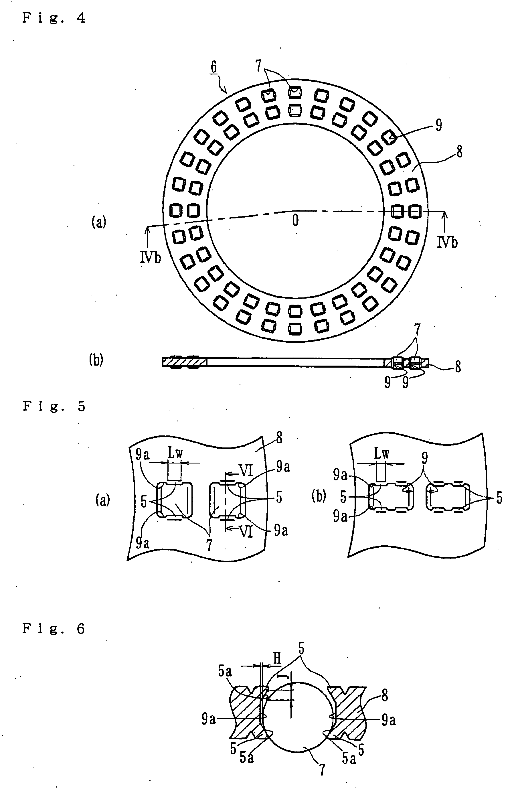
[0057]FIG. 4(a) is a plan view of a double row thrust needle roller bearing of the present invention. FIG. 4(b) is a cross-sectional view taken along a line IVb-O-IVb in FIG. 4(a). FIG. 5(a) is a partial enlarged view of FIG. 4(a). FIG. 5(b) is a similar partial enlarged view of a modified embodiment of FIG. 5(a). FIG. 6 is a cross-sectional view taken along a line VI-VI in FIG. 4(a).

[0058] The double row thrust needle roller bearing 6 comprises a plurality of needle rollers 7 and a cage 8 to hold the needle rollers 7 at a predetermined pitch in the circumferential direction. Similar to the first embodiment, the cage 8 is made by cutting soft metal materials such as copper alloy. Some examples are high tensile brass casting (JIS CAC 3 etc.), aluminum / bronze casting (JIS CAC 7 etc.), aluminum, aluminum alloy, or aluminum alloy casting (JIS AC etc.). The cage 8 has a plurality of pockets 9 each formed in a rectangular configuration with a length of its longitudinal (radial) side longe...

third embodiment

[0064]FIG. 7 is a plan view of a double row thrust needle roller bearing of the present invention. Similar to the second embodiment (FIG. 4), this embodiment has a double row pockets of radially outer and inner rows, respectively, of same number. However, the arrangement of the pockets is different.

[0065] The double row thrust needle roller bearing shown in FIG. 7(a) includes a plurality of needle rollers 7 and an annular cage 10 to hold the needle rollers 7 at a predetermined pitch in the circumferential direction. Similar to the previously described embodiments, the cage 10 is made by cutting soft metal materials such as copper alloy. Examples are high tensile brass casting (JIS CAC 3 etc.), aluminum / bronze casting (JIS CAC 7 etc.), aluminum, aluminum alloy, or aluminum alloy casting (JIS AC etc.). The cage 10 has a plurality of pockets 11. Each pocket is formed as a rectangular configuration with a length of its longitudinal (radial) side longer than that of each needle roller 7....


PUM


Abstract

A double row thrust needle roller bearing, which can suppress differential slippage of the needle rollers under severe working conditions to improve its durability without increasing processing cost for majority variety/minority lot production, has a plurality of needle rollers (2) arranged in at least two rows in a radial direction and an annular cage (3) formed with a plurality of pockets (4) to hold the needle rollers (2). Each pocket (4) is formed in a rectangular configuration with a length of its radial side longer than that of each needle roller (2). A length of the pockets circumferential side is larger than the diameter of each needle roller (2). Each needle roller (2) is held within each pocket (4) of the cage (3) by nailed portions (5). The nailed portions (5) are formed near radially extending side walls (4a) of the pockets (4) at either sides of each needle roller (2) along its longitudinal direction. The nailed portions (5) are formed by plastically deforming the cage (3) at a substantially middle portion of the longitudinal length of the needle roller (2). Thus, each nailed portion (5) overhangs into the pocket (4) over the needle roller (2).

Description

CROSS-REFERENCE TO RELATED APPLICATION [0001] This application claims priority to Japanese Patent Application No. 2004-310713, filed Oct. 26, 2004, which application is herein expressly incorporated by reference. FIELD OF THE INVENTION [0002] The present invention relates to a double row thrust needle roller bearings used in automatic transmissions, compressors for vehicle air conditioner, continuously variable transmissions, electric brakes and the like. Although “a needle roller” is classified in Japanese Industrial Standards (JIS) as “a cylindrical roller having a diameter less than 5 mm and a ratio of length / diameter of 3˜10”, the term “needle roller”, used herein, has a broader meaning without being limited to the definition of JIS. In other word, it should be appreciated that the term “needle roller” in this specification includes both “long cylindrical roller” and “cylindrical roller” defined in JIS. BACKGROUND OF THE INVENTION [0003] The thrust needle roller bearing includes...

Claims


Application Information

Patent Timeline
IPC IPC(8): F16C33/46
CPCF16C19/305F16C33/4635F16C33/4676F16C33/48F16C2300/02
Inventor YAMAMOTO, KAZUYUKIOBAYASHI, KOUSUKE
Owner NTN CORP
Why Eureka
Try Eureka