Radio communication apparatus and radio communication method

a radio communication and radio communication technology, applied in the field of radio communication apparatus and radio communication method, can solve the problems of low mcs level, reduced throughput of the entire system, and subcarriers with low reception power may be assigned, so as to improve the throughput of the own cell and neighboring cells

Active Publication Date: 2006-04-27
OPTIS WIRELESS TECH LLC
View PDF31 Cites 71 Cited by
  • Summary
  • Abstract
  • Description
  • Claims
  • Application Information

AI Technical Summary

Benefits of technology

[0020] It is an object of the present invention to provide a radio communication apparatus and radio communication method that improve throughput of the own cell and neighboring cells.

Problems solved by technology

However, above described conventional examples 1 and 2 have a problem that subcarriers having low reception power may be assigned.
According to this method, it is possible to transmit data with an MCS according to a propagation situation of subcarriers, but as shown in FIG. 6, subcarriers having low reception power (in a bad propagation situation) are assigned, resulting in a low MCS level.
In such a system, the number of subcarriers used in the own cell determines interference with neighboring cells and a large amount of interference with neighboring cells will cause the throughput of the entire system to reduce.

Method used


Image

  • Radio communication apparatus and radio communication method
  • Radio communication apparatus and radio communication method
  • Radio communication apparatus and radio communication method

Examples


embodiment 1

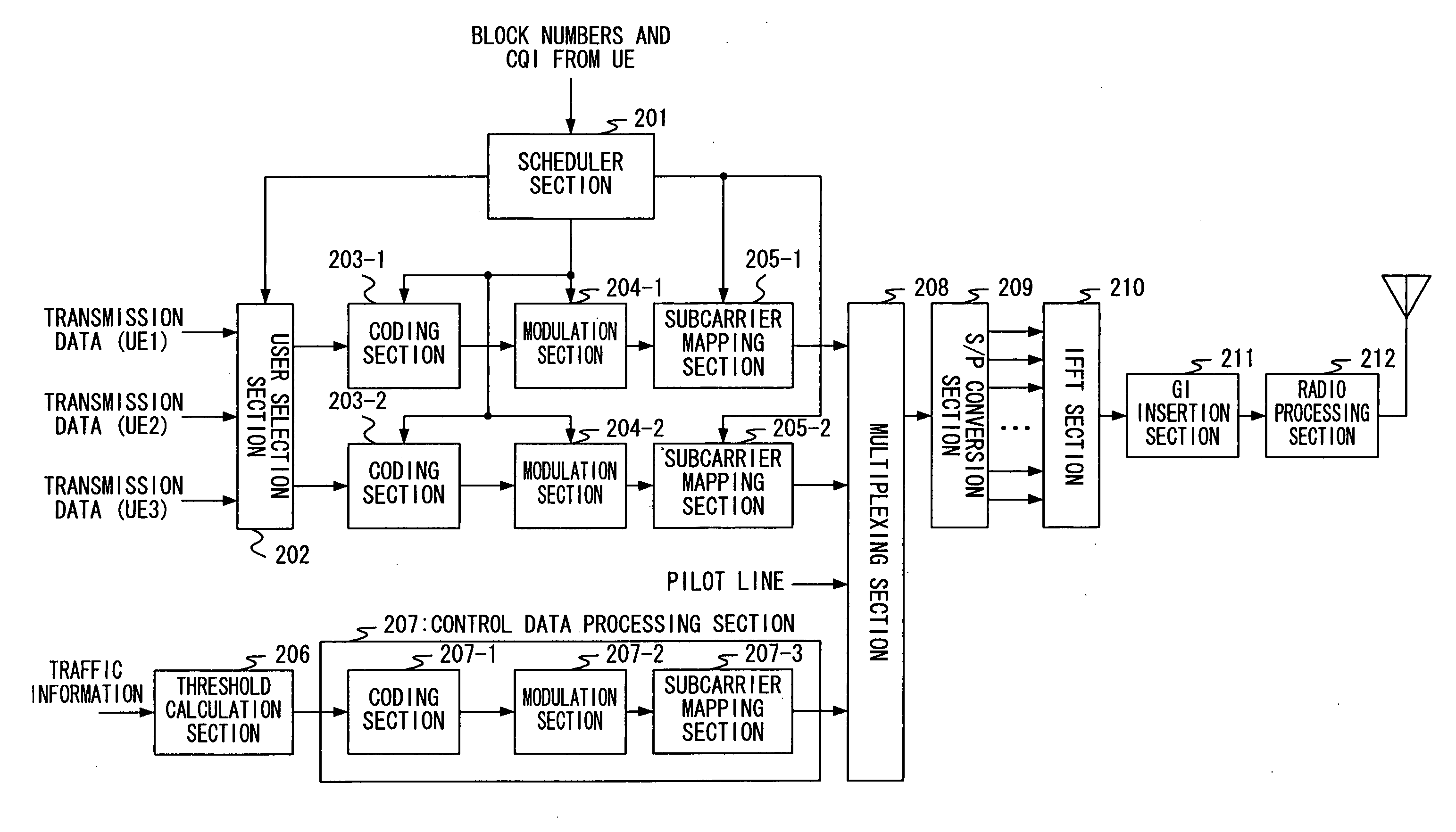
[0050]FIG. 9 is a block diagram showing the configuration of a transmission system of a base station apparatus according to Embodiment 1 of the present invention. In this figure, a scheduler section 201 determines (scheduling) to which communication terminal apparatus transmission in the next frame is carried out based on a CQI reported from each communication terminal apparatus in communication and outputs the determined scheduling information to a user selection section 202. As an algorithm of this scheduling, Max C / I, Proportional Fairness, etc., is available. Furthermore, when a user signal to be transmitted is determined through the scheduling, a modulation scheme and coding rate (MCS: Modulation and Coding Scheme) are assigned to the user signal and the assigned MCS is notified to coding sections 203-1, 203-2 and modulation sections 204-1, 204-2. Furthermore, at the same time the scheduler section 201 receives a report on usable block numbers from each communication terminal a...

embodiment 2

[0077] Embodiment 1 has described the case where usable blocks are selected based on a threshold decision on CIRs and the threshold is controlled according to an amount of traffic in the own cell and neighboring cells. Embodiment 2 of the present invention will describe a case where usable blocks are selected within a predetermined number of blocks and the number of blocks is determined according to an amount of traffic.

[0078]FIG. 15 is a block diagram showing the configuration of a transmission system of a base station apparatus according to Embodiment 2 of the present invention. However, components in FIG. 15 common to those in FIG. 9 are assigned the same reference numerals as those in FIG. 9 and detailed explanations thereof will be omitted. What FIG. 15 differs from FIG. 9 is that the threshold calculation section 206 has been changed to an assignment block number calculation section 801.

[0079] The assignment block number calculation section 801 calculates the number of block...

embodiment 3

[0091] Embodiment 3 of the present invention will describe a case where blocks available to a communication terminal apparatus is predetermined according to an amount of traffic in the own cell and neighboring cells and blocks to be used are selected according to the CIR threshold explained in Embodiment 1.

[0092]FIG. 18 is a block diagram showing the configuration of a transmission system of a base station apparatus according to Embodiment 3. However, the components in FIG. 18 common to those in FIG. 9 are assigned the same reference numerals as those in FIG. 9 and detailed explanations thereof will be omitted. What FIG. 18 differs from FIG. 9 is that a specified block determining section 1101 is added and the scheduler section 201 is changed to a scheduler section 1102.

[0093] The threshold calculation section 206 calculates a CIR threshold for deciding usable blocks at a communication terminal apparatus based on information on the traffic in the own cell and neighboring cells. Th...


PUM


Abstract

A CIR measuring section 307 measures CIRs of all blocks received and a block selection section 308 makes a threshold decision based on the CIR measurement result and threshold information according to an amount of traffic in the own cell and neighboring cells. As a result of the threshold decision, blocks whose CIRs exceed the threshold are regarded as usable blocks. A CIR averaging section 309 averages the CIRs of the usable blocks and a CQI generation section 310 generates a CQI based on the CIR average value. The CQI generated and selected block numbers are reported to a base station apparatus. This allows the throughput of the own cell and neighboring cells to be improved.

Description

TECHNICAL FIELD [0001] The present invention relates to a radio communication apparatus and radio communication method in a multicarrier transmission, and is suitable for use in, for example, an OFDM (Orthogonal Frequency Division Multiplex) communication terminal apparatus. BACKGROUND ART [0002] In a conventional W-CDMA (Wideband-Code Division Multiple Access) mobile communication system, a downlink high-speed packet transmission scheme (HSDPA: High Speed Downlink Packet Access) is being developed under which a high-speed, large-capacity downlink channel is shared among a plurality of communication terminal apparatuses and packet data is transmitted from a base station apparatus to a communication terminal apparatus at high speed. [0003] Here, HSDPA in a W-CDMA system will be explained briefly. A communication terminal apparatus measures a reception CIR (Carrier to Interference Ratio) and reports information (e.g., CQI: Channel Quality Indicator) indicating a downlink channel condi...

Claims


Application Information

Patent Timeline
Patent Type & Authority Applications(United States)
IPC IPC(8): H04B17/00H04J11/00H04B7/26H04B17/24H04B17/309H04L1/00H04L1/20H04W16/02H04W24/00H04W24/10H04W72/04
CPCH04L1/0003H04L1/0021H04L1/0026H04L1/20H04L5/0007H04L5/006H04L5/0094H04W24/10
Inventor NISHIO, AKIHIKOHIRAMATSU, KATSUHIKO
Owner OPTIS WIRELESS TECH LLC
Why Eureka
Try Eureka