Surgical device guide for use with an imaging system

a surgical device and imaging system technology, applied in the field of tissue treatment systems, can solve the problems of tumor reoccurrence, difficult procedure, and physical limitations that frequently prevent inline placement of ablation and ultrasound probes

Inactive Publication Date: 2006-04-27
CILAG GMBH INT
View PDF107 Cites 114 Cited by
  • Summary
  • Abstract
  • Description
  • Claims
  • Application Information

AI Technical Summary

Problems solved by technology

However, physical limitations frequently prevent inline placement of the ablation and ultrasound probes.
Placement of the ablation probe outside of the image plane of the ultrasound probe adds to the mental challenge of three-dimensional (3D) planning and makes the procedure difficult.
Leaving unablated tumor can result in tum

Method used


Image

  • Surgical device guide for use with an imaging system
  • Surgical device guide for use with an imaging system
  • Surgical device guide for use with an imaging system

Examples


second embodiment

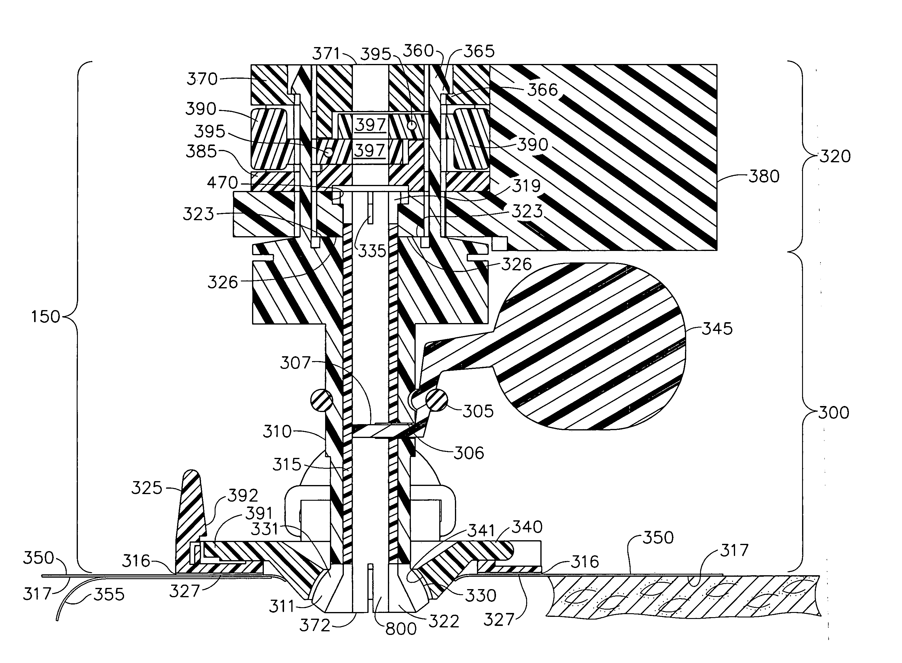
[0039] Referring now to FIGS. 3A and 3B, in a first aspect of the invention, the positioner 150 consists of a stem assembly 300 and a depth stop assembly 320. Within the stem assembly is an outer stem 310 that includes a semispherical portion 331. Semispherical, as used herein, means having the shape of a portion of a sphere. The semispherical portion 331 has a stem radius 330 with slots 311 that enable the stem radius 330 to nestle into a corresponding frame radius 341 of frame 340. The stem radius 330 and the frame radius 341 function similarly to a ball joint, allowing the outer stem 310 to rotate with respect to the frame 340. In an alternative embodiment, the outer stem 310 may be connected to the frame 340 by a ball joint.

[0040] An inner stem 315 including a stem flare feature 322 that mates with the inside surface of the semispherical portion of the outer stem 331 is positioned within the outer stem 310. The inner stem 315 has a channel 800 into which a needle-like surgical d...

first embodiment

[0045] As in the first aspect of the invention, the knob 380′ has a ramp surface 326′ that engages an outer stem ramp surface 323′. Grasping the knob 380′ and rotating it to one side draws the inner stem 315′ through the outer stem and, consequently, draws a semispherical portion 331′ of the outer stem into a mating frame radius 341′ of a frame 340′. Slots 311′ allows the stem radius 330′ of a stem flare feature 322′ of the outer stem 310′ to expand and reactive forces fix the angular position of the outer stem 310′ in the chosen orientation, locking the trajectory of any inserted surgical device.

[0046] In one embodiment, the frame 340′ is attached to a holder 325′ by hinge pin 342′ feature that mates with a hinge recess 343′ of a holder 325′. A snap lever 391′ engages a snap catch 392′ to secure the frame 340′ within the holder 325′. The holder 325′ has a clip end 303′ which may be attached to the mating receptacle 304′ of a fixation device 190′ to hold the positioner 150′ in place...

third embodiment

[0051] Referring now to FIGS. 8A and 8B, a first aspect of the invention includes a sliding disk 310″ which allows the surgeon to adjust the insertion point after-the holder 325 has adhered to the patient. As used herein, insertion point is the point on the skin of the patient where the ablation probe is inserted. In the embodiment depicted in FIGS. 8A and 8B, the stem assembly 200″ has a single stem 210″ with a semispherical portion 231″ at its distal end. The semispherical portion 231″ has a stem radius 230″ that nestles into a corresponding frame radius 241″ of a frame 240″ and a bottom surface that bears against patient 250″. The stem radius 230″ and the frame radius 241″ function similarly to a ball joint, allowing the stem 210″ to rotate with respect to the frame 240″. Therefore, the center of angular rotation of the stem radius 230″ is at or near the skin of the patient 250″ without significant skin deformation, maximizing the range of motion through a small incision in the s...


PUM


Abstract

A device and method useful for guiding insertion of a surgical device with image guided surgery. The device includes a base that may be connected to a fixation device to hold the device in place, and a guide for the surgical device. The guide is connected to the base by a semispherical ball joint, which allows the trajectory of the guide to be adjusted. The device includes an adjustable depth stop that controls the distance the surgical device is inserted into the patient. A positional indicator is attached to the depth stop. An insertion indicator signals when the depth stop is set so as to limit the insertion distance to that necessary to treat the target tissue within the patient.

Description

FIELD OF THE INVENTION [0001] The present invention is generally related to a system for treating tissue with a surgical device inserted into the body and guided by an ultrasound or other imaging device. BACKGROUND OF THE INVENTION [0002] In one method of treating tumors or lesions in solid organs such as the kidney or the liver, a surgical device such as a radio frequency (RF) ablation probe is placed into the tumor and the tumor cells are destroyed using RF energy. Placement of the ablation probe is accomplished using an imaging system, such as ultrasound imaging. An ultrasound imaging system generates a two-dimensional (2D) image, effectively allowing the doctor or surgeon to view the tissue within the image plane of the ultrasound probe. If the ultrasound probe is positioned such that the axis of the ablation and ultrasound probes are co-aligned, the surgeon can observe the placement of the ablation probe in the tissue on the ultrasound image. However, physical limitations frequ...

Claims


Application Information

Patent Timeline
IPC IPC(8): A61B19/00A61B17/00
CPCA61B17/3403A61B17/3462A61B17/3494A61B19/201A61B19/26A61B19/5212A61B19/5244A61B2017/320052A61B2017/3405A61B2017/3407A61B2017/3492A61B2019/505A61B2019/507A61B2019/5251A61B2019/5276A61B2019/547A61B34/20A61B90/361A61B90/50A61B90/11A61B2034/105A61B2034/107A61B2034/2051A61B2090/378A61B2090/397
Inventor VLEGELE, JAMES W.GILL, ROBERT PERRIN
Owner CILAG GMBH INT
Why Eureka
Try Eureka