Construction improvement of the piston valve in compressing pump

a technology of piston valve and compressing pump, which is applied in the direction of machines/engines, liquid fuel engines, positive displacement liquid engines, etc., can solve the problems of substantial drawbacks in the foregoing procedure, prolong the service life of anti-backflow plastic gaskets, and improve the compressing and discharging efficiency of integral compressing pumps.

Inactive Publication Date: 2006-05-04
CAI YING LIN +1
View PDF12 Cites 23 Cited by
  • Summary
  • Abstract
  • Description
  • Claims
  • Application Information

AI Technical Summary

Benefits of technology

[0008] The primary object of the present invention is to provide a construction improvement of the piston valve in compressing pump, wherein, The discharge base, which is built in the center of the piston valve, is contrived into planar shape; The anti-backflow plastic gasket, which is contrived into 3-blade planar shape to entirely cover said discharge base, has a gap cleft created between each blade so that each said blade can closely block exactly each corresponding inlet slots on said discharge base respectively; By means of gap cleft created between each blade, each said blade is flexibly enable to act smoothly during the procedure of constantly alternate open-and-shut discharge without any interference each other; the drawback of leakage and pressure loss or failure can be avoided as the distortion of each said blade will never happen again; thus not only the serving life of said anti-backflow plastic gasket can be prolonged, but also the compressing and discharging efficiency of integral compressing pump can be further enhanced.

Problems solved by technology

However, there are some substantial drawbacks in the foregoing procedure as below:

Method used


Image

  • Construction improvement of the piston valve in compressing pump
  • Construction improvement of the piston valve in compressing pump
  • Construction improvement of the piston valve in compressing pump

Examples


Embodiment Construction

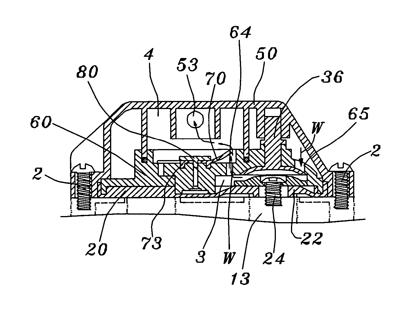
[0021] Referring to FIG. 8 to FIG. 10, a construction improvement of the piston valve in compressing pump of the present invention comprising a piston valve and a anti-backflow plastic gasket, Wherein the discharge base 61, which is built in the center of the piston valve 60 of the compressing pump with direction towards the upper hood 50, is contrived into planar shape; An orientating lump 62, which is created in the top center of said discharge base 61 and being punched an orientating hole 63 at its center, has some discharge spouts 64 punched in each of three areas with 120 degree of included angle around itself; Some inlet slots 65, which are created on the peripheral of said discharge base 61 in corresponding with each said discharge spouts 64, has some inverse flare piston slice 36 punched at each center of their own so that to block each said corresponding inlet slots 65; The anti-backflow plastic gasket 70, which is contrived into 3-blade planar shape to entirely cover said ...


PUM


Abstract

The present invention relates to a construction improvement of the piston valve in compressing pump with features as below: The discharge base, which is built in the center of the piston valve, is contrived into planar shape; Some discharge spouts are created on said discharge base in corresponding with each said inlet slots; An orientating lump is created in the top center of said discharge base and being punched an orientating hole at its center; The anti-backflow plastic gasket, which is contrived into 3-blade planar shape to entirely cover the top of said discharge base, has a gap cleft created between each blade so that each said blade can closely block exactly each said corresponding inlet slots on said discharge base respectively; During each said wobble wheels of the compressing pump pushing said diaphragm in turns, the water flow, which coming from each said inlet slot at each area, will continuously runs into each said discharge spout at each area in said discharge base by turns so that each blade on said anti-backflow plastic gasket working up-open and down-shut action by turns as well, thus it really achieves the open-and-shut effect of each said discharge spout at each area; Therefore, not only the drawback of leakage and pressure loss or failure can be prevented, but also the serving life of said anti-backflow plastic gasket can be prolonged, thus the compressing and discharging efficiency of integral compressing pump can be further enhanced.

Description

FIELD OF THE PRESENT INVENTION [0001] The present invention relates to the discharge of the piston valve in compressing pump exclusively used in the reverse osmosis purification; more particularly a construction improvement being contrived to prevent the drawback of said compressing pump from leakage and pressure failure or loss. BACKGROUND OF THE PRESENT INVENTION [0002] Refer to FIG. 1 through FIG. 6, a conventional compressing pump exclusively used in the reverse osmosis purification comprises: a motor 10 with an upper hood chassis 11 being built on the output shaft (not shown in the figure) of said motor 10, and multiple screw bores 12 are perforated on the peripheral of said upper hood chassis 11; a plurality of wobble wheels 13, which are movably placed in said upper hood chassis 11, are drived by the output shaft of said motor 10 such that being transformed into radial reciprocating motion; a diaphragm 20 covers on said upper hood chassis 11; a piston valve 30 is embedded in ...

Claims


Application Information

Patent Timeline
Patent Type & Authority Applications(United States)
IPC IPC(8): F16J1/00
CPCF04B53/1065F04B39/00F04B39/10
Inventor HSU, CHAO FOUCAI, YING LIN
Owner CAI YING LIN
Why Eureka
Try Eureka