Ultrasonic rod waveguide-radiator

a waveguide-radiator and ultrasonic technology, applied in the direction of mechanical vibration separation, instruments, machines/engines, etc., can solve the problems of affecting the operation regime affecting the quality of operation, and affecting the operation of the entire waveguide-radiator. , to achieve the effect of improving the operational life of the waveguide-radiator, improving the acoustic energy radiated, and improving the quality of operation

Active Publication Date: 2006-05-04
INDAL SONOMECHANICS +1
View PDF28 Cites 200 Cited by
  • Summary
  • Abstract
  • Description
  • Claims
  • Application Information

AI Technical Summary

Benefits of technology

[0008] It is therefore a principal object and advantage of the present invention to provide a waveguide-radiator that is free from the drawbacks enumerated above, having an exit diameter close to the entrance diameter, and a gain factor much higher than unity, and having the following objectives:
[0009] 1. To improve the quality of operation and to increase the operational life of a wave guide-radiator.
[0010] 2. To increase the acoustic energy radiated into a load by a waveguide-radiator.
[0011] 3. To increase the reliability of fastening various cutting and other tools on the waveguide radiator.
[0012] 4. To increase the available radiation surface and the uniformity of the distribution of acoustic energy throughout the volume of an ultrasonic reactor.
[0013] 5. To conduct ultrasonic treatment of the internal surfaces of thin extended channels and tubes.

Problems solved by technology

Furthermore, a considerable increase in the amplitude of vibrations is not always justified from the technological point of view.
When the waveguide-radiator exit diameter is larger than this value, radiation via the waveguide-radiator's side surfaces begins to have a strong effect, and calculation of the waveguide's acoustic properties becomes difficult to predict.
This leads to a disruption of the regime of the operation of the entire waveguide-radiator.
Thus, a direct acoustic calculation of the waveguide-radiator as a waveguide of longitudinal waves becomes inaccurate.
Second, the length of the specified exit section is small as compared with its diameter and, therefore, in this section the degree of strain (and, as a consequence, stress) along the section length is high, which substantially decreases the operational life span of such a waveguide-radiator at high amplitude.

Method used


Image

  • Ultrasonic rod waveguide-radiator
  • Ultrasonic rod waveguide-radiator
  • Ultrasonic rod waveguide-radiator

Examples


Embodiment Construction

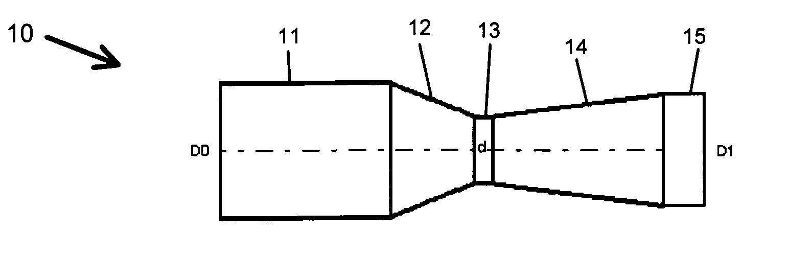
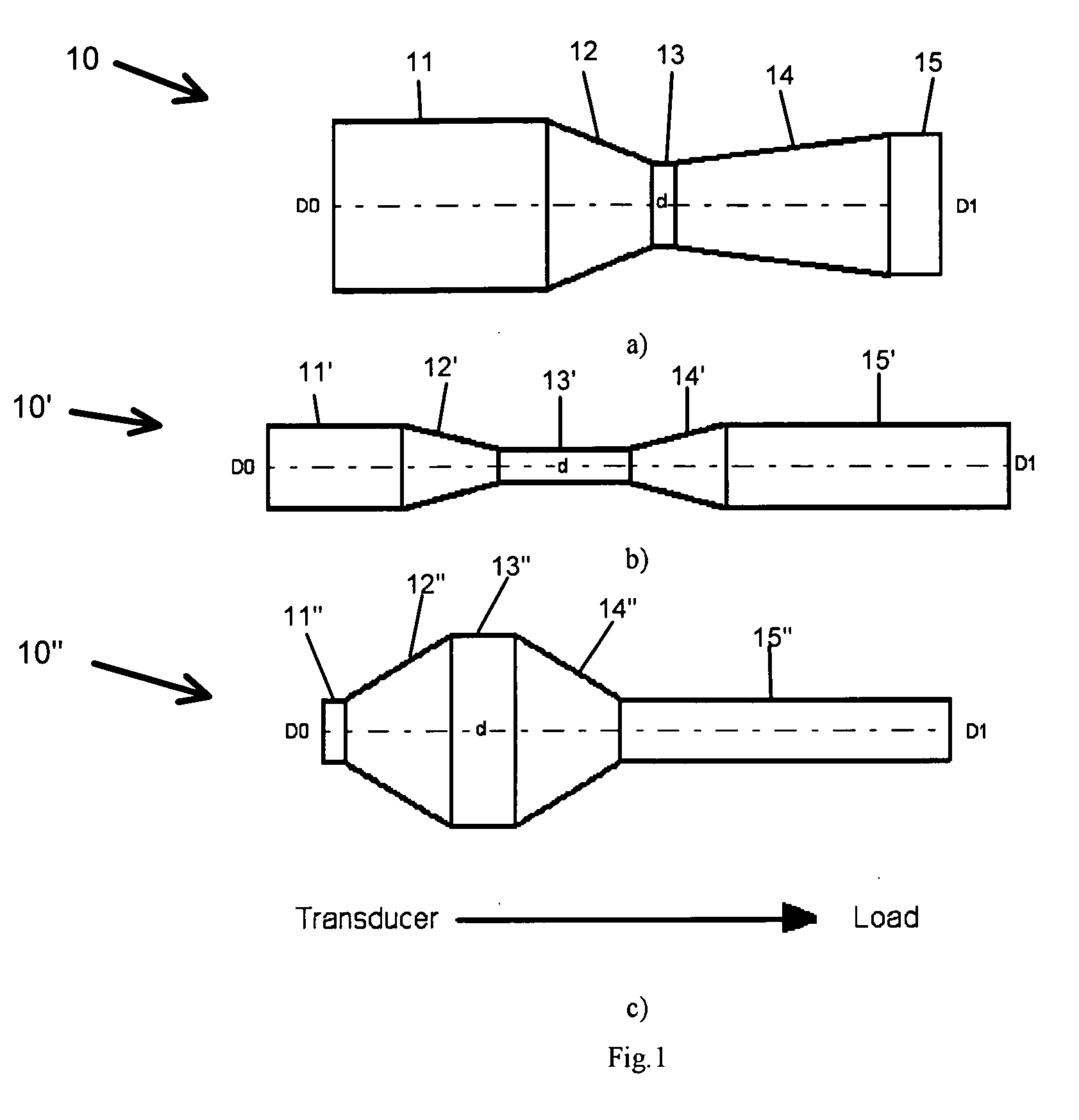
[0027] Referring now to the drawings, wherein like reference numerals refer to like parts throughout, there is seen in FIG. 1 a waveguide-radiator 10, 10′, 10″ according to the present invention. The improvement of the quality of operation and an increase in the operational life of a waveguide-radiator are achieved through the use of a waveguide-radiator shown in FIG. 1. The waveguide-radiator consists of five sections 11-15, 11′-15′, 11″-15″ in a combination of cylindrical sections 11, 13, 15, 11′, 13′, 15′, 11″, 13″, 15″ and sections of variable cross-section 12, 14, 12′, 14′, 12″, 14″, all made of metal. The cylindrical sections and variable cross-section sections alternate in series and are acoustically rigidly connected between themselves. The geometrical dimensions of these sections are selected using a known method of acoustic calculation (Rayleigh equation) in such a way that their total length is equal to the value that is a multiple of half the length of an acoustic wave i...


PUM


Abstract

The present invention comprises an ultrasonic resonant rod waveguide-radiator with at least three cylindrical sections, one of which is an entrance section having a planar entrance surface and another of which is an exit section having a planar exit surface, and at least two sections having a variable cross-section. The cylindrical sections and sections of variable cross-section are arranged in alternating fashion and connected to each other acoustically rigidly. The dimensions of the cylindrical sections and the sections of variable cross-section are selected so that the gain of the waveguide-radiator is significantly greater than unity and the strain created by passage of ultrasonic waves through the waveguide-radiator is minimized, increasing the operational life of the waveguide-radiator and maximizing the amount of useful energy transmitted by the waveguide-radiator.

Description

BACKGROUND OF THE INVENTION [0001] 1. Field of the Invention [0002] The present invention relates to the field of ultrasonic equipment and can be used in different technological devices for the transmission of acoustic energy into an acoustic load, for example, in heat and mass transfer processes, plastic welding, metal treatment, etc. [0003] 2. Description of Prior Art [0004] Acoustic energy is usually transmitted into an acoustic load (liquid, polymeric or hard material) using an ultrasonic waveguide-radiator connected to an electro-acoustic transducer (magnetostrictive or piezoelectric). The tasks of the waveguide-radiator are to increase the amplitude of the transducer vibrations A up to the level necessary in a given technology, to match the energy of a transducer to an acoustic load, to uniformly distribute radiated acoustic energy throughout the volume of the medium being treated, and / or to facilitate reliable fastening of cutting and other tools to the waveguide radiator. Ma...

Claims


Application Information

Patent Timeline
Patent Type & Authority Applications(United States)
IPC IPC(8): F01N1/02F01N1/00
CPCB06B3/00A61B17/32A61B17/320068A61B2017/22018
Inventor PESHKOVSKIY, SERGEY L.FRIEDMAN, MICHAEL L.HAWKINS, WILTON A.
Owner INDAL SONOMECHANICS
Why Eureka
Try Eureka