Analyte sensor with insertion monitor, and methods

an analyte sensor and monitor technology, applied in the field of analyte sensors, can solve the problems of inconvenient patient procedures, and achieve the effect of efficient and reliable methods

Inactive Publication Date: 2006-05-04
ABBOTT DIABETES CARE INC
View PDF103 Cites 582 Cited by
  • Summary
  • Abstract
  • Description
  • Claims
  • Application Information

AI Technical Summary

Benefits of technology

[0015] One method of forming a sensor, as described above, includes forming at least one working electrode on a first substrate and forming at least one counter or counter / reference electrode on a second substrate. A spacer layer is disposed on either the first or second substrates. The spacer layer defines a chamber into which a sample can be drawn and held when the sensor is completed. A redox mediator and / or second electron transfer agent can be disposed on the first or second substrate in a region that will be exposed within the sample chamber when the sensor is completed. The first and second substrates are then brought together and spaced apart by the spacer layer with the sample chamber providing access to the at least one working electrode and the at least one counter or counter / reference electrode. In some embodiments, the first and second substrates are portions of a single sheet or continuous web of material. The invention includes particularly efficient and reliable methods for the manufacture of these sensors.

Problems solved by technology

These procedures are inconvenient for the patient, and often painful, particularly when frequent samples are required.
However, lancing the body in the preferred regions typically produces submicroliter samples of blood, because these regions are not heavily supplied with near-surface capillary vessels.

Method used


Image

  • Analyte sensor with insertion monitor, and methods
  • Analyte sensor with insertion monitor, and methods
  • Analyte sensor with insertion monitor, and methods

Examples


first embodiment

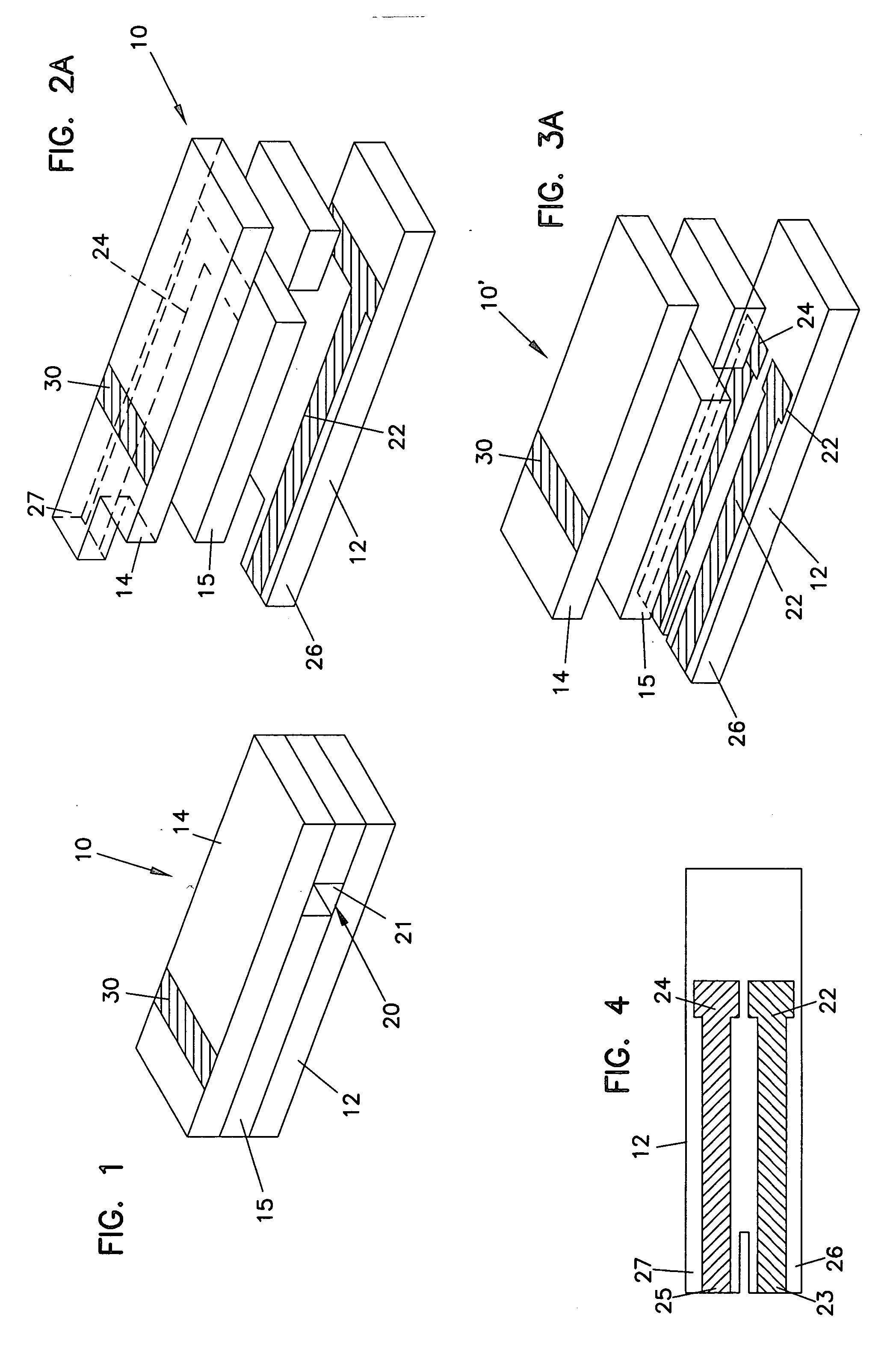
[0052] Referring to the Drawings in general and FIGS. 1 and 2A in particular, a sensor strip 10 is schematically illustrated. Sensor strip 10 has a first substrate 12, a second substrate 14, and a spacer 15 positioned therebetween. Sensor strip 10 includes at least one working electrode 22 and at least one counter electrode 24. Sensor strip 10 also includes insertion monitor 30.

Sensor Strips

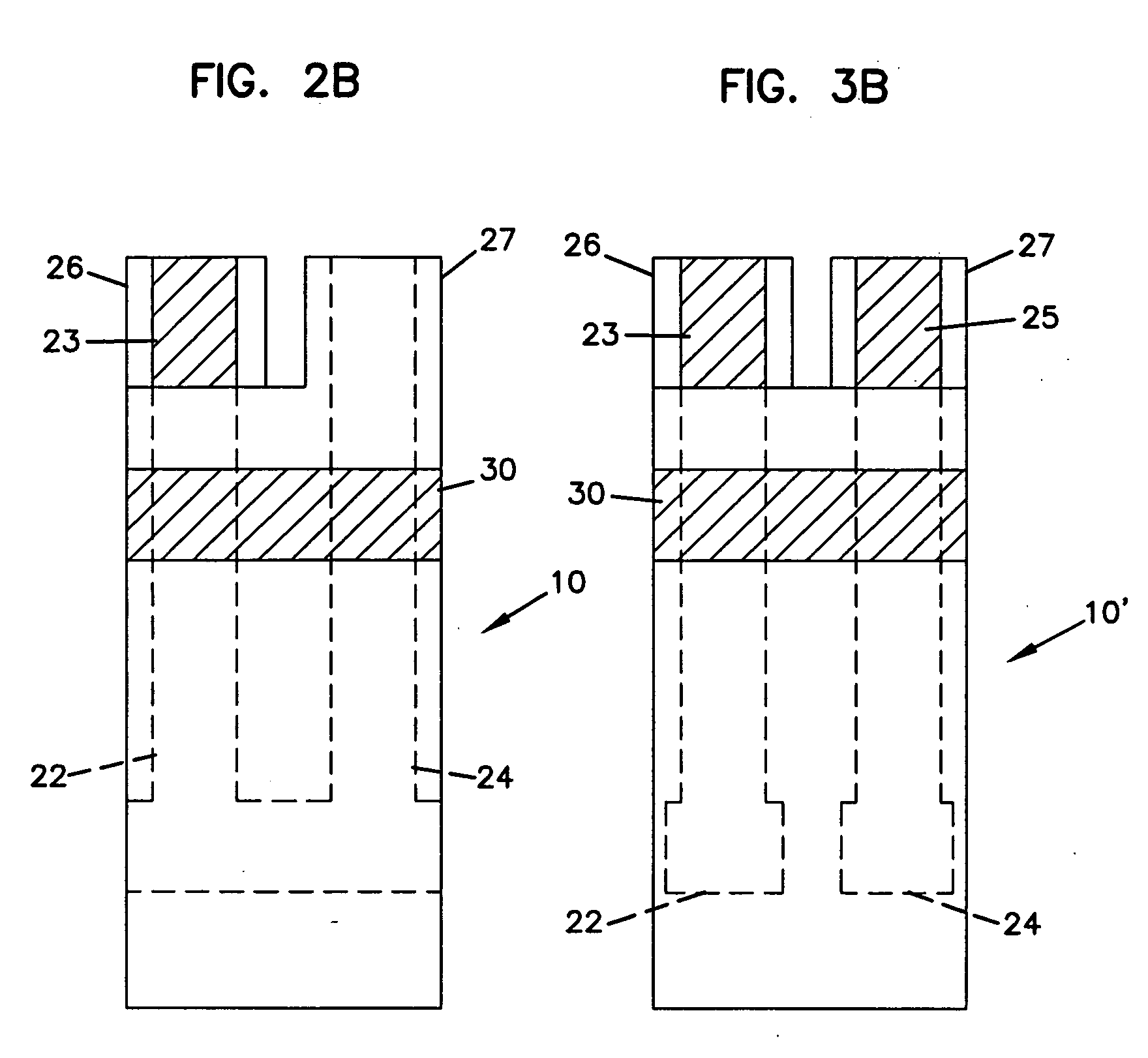
[0053] Referring to FIGS. 1, 2A and 2B in particular, sensor strip 10 has first substrate 12, second substrate 14, and spacer 15 positioned therebetween. Sensor strip 10 includes working electrode 22, counter electrode 24 and insertion monitor 30. Sensor strip 10 is a layered construction, in certain embodiments having a generally rectangular shape, i.e., its length is longer than its width, although other shapes are possible as well. Sensor strip 10′ of FIGS. 3A, 3B and 4 also has first substrate 12, second substrate 14, spacer 15, working electrode 22, counter electrode 24 and insertion monit...

second embodiment

[0065] At least one working electrode is positioned on one of first substrate 12 and second substrate 14. In all of FIGS. 2A though 4, working electrode 22 is illustrated on substrate 12. Working electrode 22 extends from the sample chamber 20 to the other end of the sensor 10 as an electrode extension called a “trace”. The trace provides a contact pad 23 for providing electrical connection to a meter or other device to allow for data and measurement collection, as will be described later. Contact pad 23 can be positioned on a tab 26 that extends from the substrate on which working electrode 22 is positioned, such as substrate 12. In one embodiment, a tab has more than one contact pad positioned thereon. In a second embodiment, a single contact pad is used to provide a connection to one or more electrodes; that is, multiple electrodes are coupled together and are connected via one contact pad.

[0066] Working electrode 22 can be a layer of conductive material such as gold, carbon, pla...


PUM

PropertyMeasurementUnit
volumeaaaaaaaaaa
volumeaaaaaaaaaa
volumeaaaaaaaaaa

Abstract

A sensor, and methods of making, for determining the concentration of an analyte, such as glucose or lactate, in a biological fluid such as blood or serum, using techniques such as coulometry, amperometry, and potentiometry. The sensor includes a working electrode and a counter electrode, and can include an insertion monitoring trace to determine correct positioning of the sensor in a connector.

Description

[0001] This application is a continuation-in-part of U.S. Ser. No. 10 / 866,477, filed Jun. 12, 2004, which is a continuation of U.S. Ser. No. 10 / 033,575, filed Dec. 28, 2001, issued as U.S. Pat. No. 6,749,740, which is a continuation of U.S. Ser. No. 09 / 434,026, filed Nov. 4, 1999, issued as U.S. Pat. No. 6,616,819, the entire disclosures of which are incorporated herein by reference.FIELD OF THE INVENTION [0002] This invention relates to analytical sensors for the detection of bioanalytes in a small volume sample, and methods of making and using the sensors. BACKGROUND [0003] Analytical sensors are useful in chemistry and medicine to determine the presence and concentration of a biological analyte. Such sensors are needed, for example, to monitor glucose in diabetic patients and lactate during critical care events. [0004] Currently available technology measures bioanalytes in relatively large sample volumes, e.g., generally requiring 3 microliters or more of blood or other biologica...

Claims


Application Information

Patent Timeline
Patent Type & Authority Applications(United States)
IPC IPC(8): G01N33/487
CPCA61B5/14532A61B5/1486A61B2562/085A61B2562/227C12Q1/006G01N33/48771
Inventor WANG, YIVIVOLO, JOSEPH A.ALVA KARINKA, SHRIDHARA
Owner ABBOTT DIABETES CARE INC
Why Eureka
Try Eureka