
Lighter-than-air aircraft and related methods for powering the same

Inactive Publication Date: 2006-05-04
HARRIS CORP
View PDF22 Cites 20 Cited by
  • Summary
  • Abstract
  • Description
  • Claims
  • Application Information

AI Technical Summary

Benefits of technology

[0008] In view of the foregoing background, it is therefore an object of the present invention to increase the efficiency at which energy is collected, stored and converted to power so that a lighter-than-air aircraft can remain aloft at high altitudes for extended periods of time without having to return to ground for refueling.
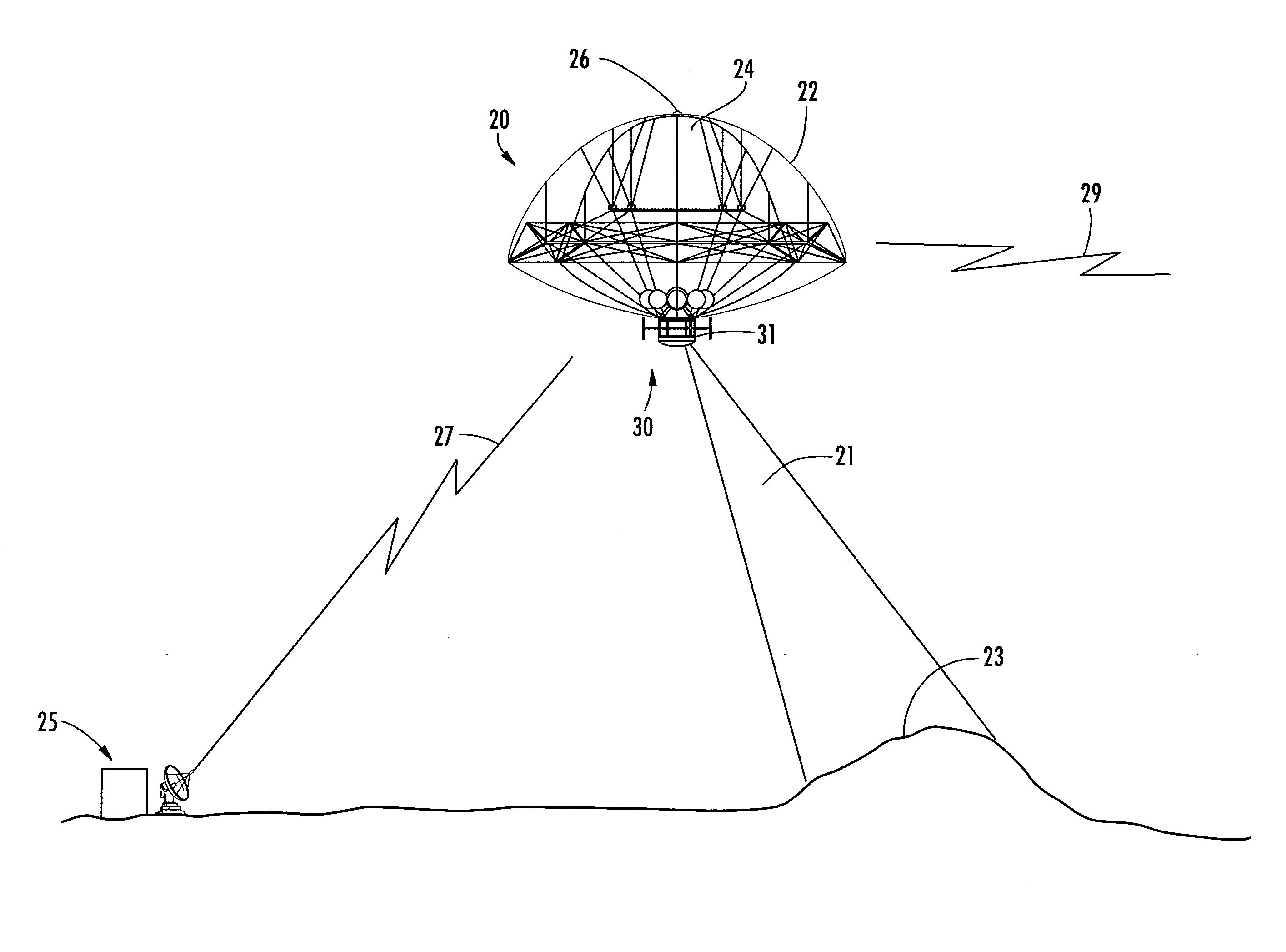
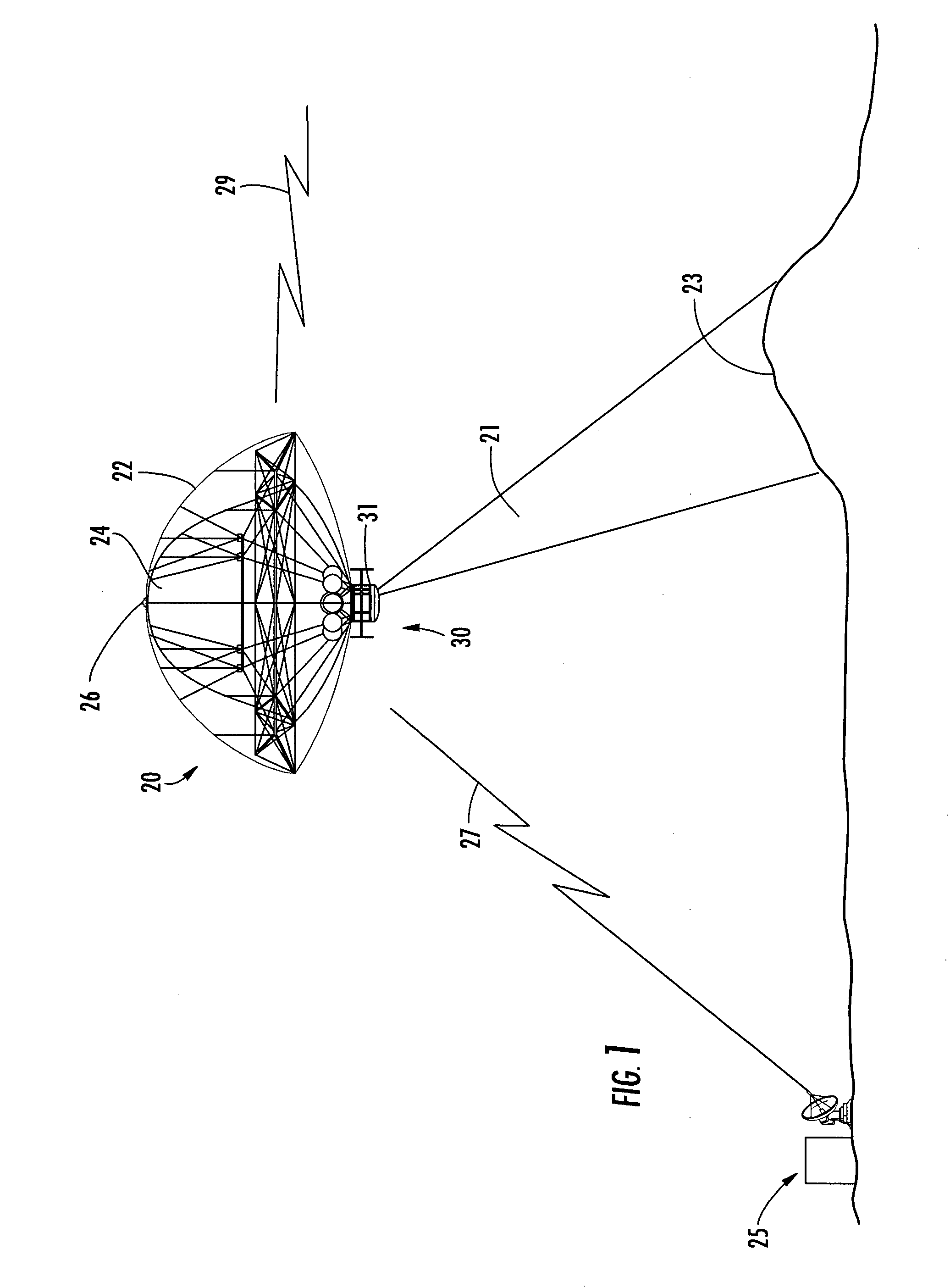
[0010] A propulsion system carried by the gas envelope orients the gas envelope so that the solar panel is oriented in the direction of the sun based upon the solar sensor. The lighter-than-air aircraft may further comprise a navigation controller cooperating with the propulsion system to move the lighter-than-air aircraft along a desired flight path while the solar panel is oriented in the direction of the sun. Pointing the solar panel in the direction of the sun independent of the desired flight path increases the efficiency at which solar energy is collected.
[0011] The lighter-than-air aircraft is capable of high-altitude station keeping within altitude and perimeter boundaries for extended periods of time. The lighter-than-air aircraft is intended to operate at an altitude of about 60,000 to 80,000 feet in the stratosphere, where it is ideal to sit, look, listen and provide surveillance and communications from a strategic perspective. This altitude allows on-board sensors to see over the horizon at least 350 miles in any direction.
[0012] Since the propulsion system orients the gas envelope so that the solar panel is oriented in the direction of the sun based upon the solar sensor, this allows the solar panel to be constantly pointing toward the sun. With the performance of the solar panel being optimized, extra solar panels do not need to be carried by the gas envelope. This advantageously reduces the overall weight and cost of the lighter-than-air aircraft.
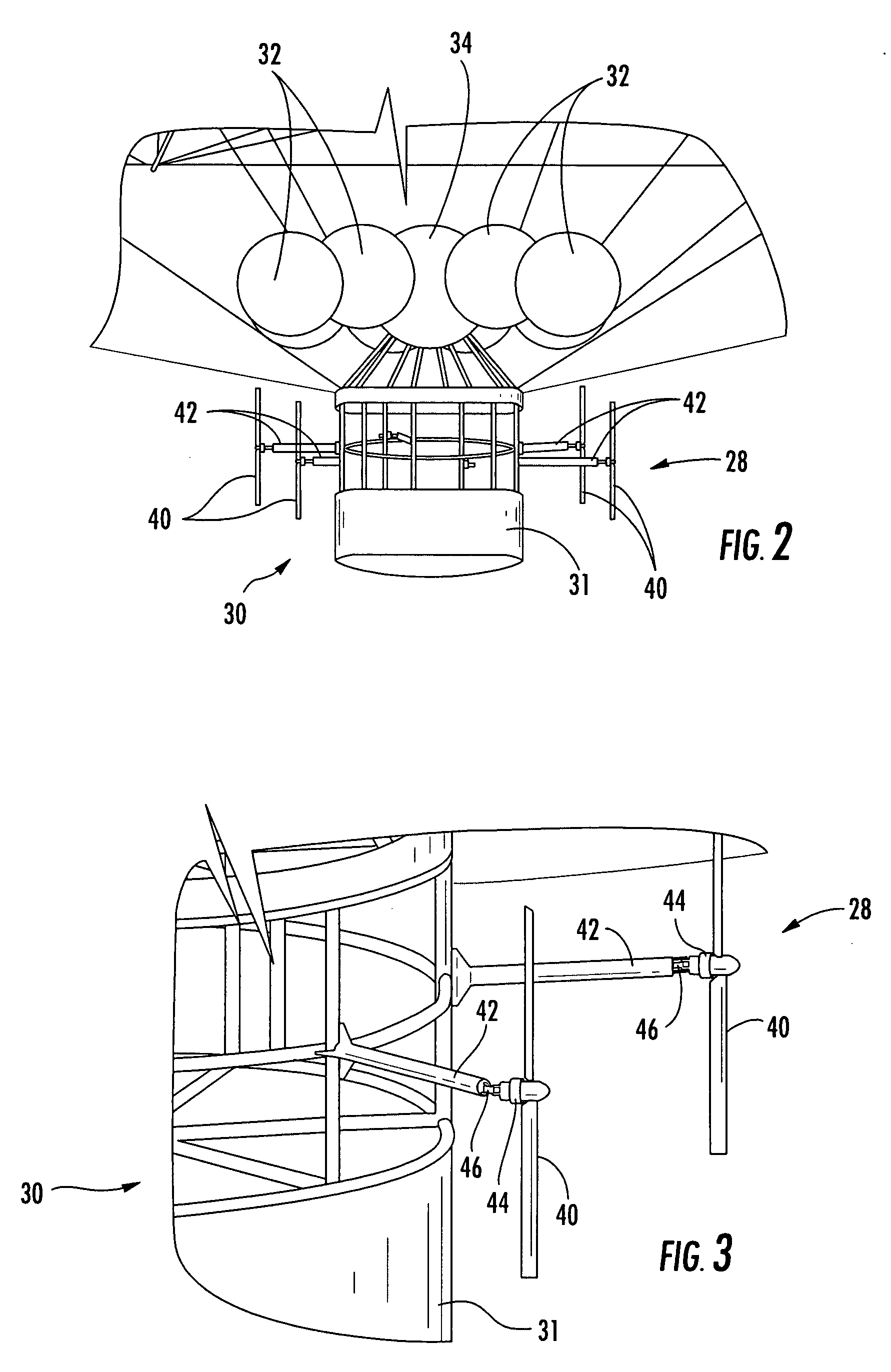
[0014] The propulsion system may comprise an electrical propulsion system. The lighter-than-air aircraft may further comprise a closed loop fuel cell carried by the gas envelope for powering the electrical propulsion system when the solar panel is not generating sufficient electricity, and having its fuel regenerated by the solar panel from its exhaust when the solar panel is generating sufficient electricity. The closed loop fuel cell advantageously increases the efficiency at which fuel is stored and converted to power so that the lighter-than-air aircraft can remain aloft at high altitudes for extended periods of time without having to return to ground for refueling.
[0016] In the retracted position, the gas envelope and gondola have less drag because of its “flat top,” and because the gondola is pulled closer to the gas envelope. This results in the gas envelope and gondola having a reduced cross section, which helps to reduce the effects of winds at the lower altitudes. Another advantage of the “flat top” design is that it allows for a significant reduction in the height of the facility constructing the lighter-than-air aircraft. Once the lighter-than-aircraft reaches its desired altitude near or above 60,000 feet, the gas envelope is fully expanded.

Problems solved by technology

Consequently, the issue is not in getting an aircraft to 60,000 feet, but in maintaining power so that the on-board sensors and electronics are continuously powered for extended periods of time, which may be from a few weeks to several months to even longer.
Although the energy provided by solar cells is adequate to power lighter-than-air aircraft while in the sunlight, the challenge is to repeatedly get through the night.
To keep a large lighter-than-air aircraft in a general location at 60,000 feet requires a significant amount of power.
One approach is to place more solar panels on the aircraft for collecting and storing the additional power, but this results in an increase of the weight of the aircraft.
The greater the weight, the greater the volume of lift gas required, which increases the amount of material necessary to contain the lift gas.
These increases in weight and volume impose additional power requirements.
However, these systems are not particularly advantageous on a lighter-than-air aircraft.

Method used


Image

  • Lighter-than-air aircraft and related methods for powering the same
  • Lighter-than-air aircraft and related methods for powering the same
  • Lighter-than-air aircraft and related methods for powering the same

Examples


Embodiment Construction

[0032] The present invention will now be described more fully hereinafter with reference to the accompanying drawings, in which preferred embodiments of the invention are shown. This invention may, however, be embodied in many different forms and should not be construed as limited to the embodiments set forth herein. Rather, these embodiments are provided so that this disclosure will be thorough and complete, and will fully convey the scope of the invention to those skilled in the art. Like numbers refer to like elements throughout, and prime, and double prime notations are used to indicate similar elements in alternative embodiments.

[0033] Referring initially to FIGS. 1-3, the lighter-than-air aircraft 20 is capable of high-altitude station keeping within altitude and perimeter boundaries for extended periods of time. The illustrated lighter-than-air aircraft 20 is in the upper stratosphere at 60,000 to 80,000 feet, for example, where it is ideal to sit, look, listen and provide s...


PUM


Abstract

A lighter-than-air aircraft includes a gas envelope for containing a buoyant gas, and a solar panel is carried by a predetermined portion of the gas envelope. A solar sensor is used for determining a direction of the sun. A propulsion system carried by the gas envelope orients the gas envelope so that the solar panel is oriented in the direction of the sun based upon the solar sensor. A navigation controller cooperates with the propulsion system to move the lighter-than-air aircraft along a desired flight path while the solar panel is oriented in the direction of the sun.

Description

FIELD OF THE INVENTION [0001] The present invention relates to the field of lighter-than-air aircraft, and in particular, to a lighter-than-air aircraft capable of remaining in the air at high altitudes for extended periods of time. BACKGROUND OF THE INVENTION [0002] High altitude, long-duration solar powered aircraft have been proposed for both commercial and military applications. For example, lighter-than-air aircraft have been proposed for cellular telephone applications. Military applications also include telecommunication applications as well as providing surveillance. [0003] There is a domain in the upper stratosphere at 60,000 feet where it is ideal to position a lighter-than-air aircraft. This altitude allows on-board sensors to see over the horizon at least 350 miles in any direction. In most such applications, long duration station keeping is essential. Consequently, the issue is not in getting an aircraft to 60,000 feet, but in maintaining power so that the on-board sens...

Claims


Application Information

Patent Timeline
IPC IPC(8): B64B1/58
CPCB64B1/14B64B1/22B64B1/30
Inventor PALMER, WILLIAM ROBERT
Owner HARRIS CORP
Learn More