Field device and method for transferring the field device's signals

a field device and signal technology, applied in the field of field devices and methods for transferring the signals of field devices, can solve the problems of battery replacement and additional wiring, and achieve the effect of easy linkage of firmware and minimal cos

Active Publication Date: 2006-05-04
YOKOGAWA ELECTRIC CORP
View PDF13 Cites 119 Cited by
  • Summary
  • Abstract
  • Description
  • Claims
  • Application Information

AI Technical Summary

Benefits of technology

[0023] The present invention is intended to solve the foregoing problems. An object of the invention, therefore, is to provide a field device whereby the device's additional information can be transmitted wirelessly without the need for battery replacement or external wiring.
[0024] Another object of the present invention is to enable the firmware of a wireless module in the field device to be developed at minimum cost and to provide a method for transferring the field device's signals whereby it can be made easy to link the firmware to applications, such as an asset management system, on the host system side.

Problems solved by technology

However, the positioner equipped with the wireless module has the following problems from the viewpoint of the electric power required for transmitting or receiving radio signals: As a power supply for the wireless module, either power supply block 17 using batteries or an external power supply needs to be used.
Hence, the problem is that the former requires battery replacement whereas the latter necessitates additional wiring.

Method used


Image

  • Field device and method for transferring the field device's signals
  • Field device and method for transferring the field device's signals
  • Field device and method for transferring the field device's signals

Examples


second embodiment

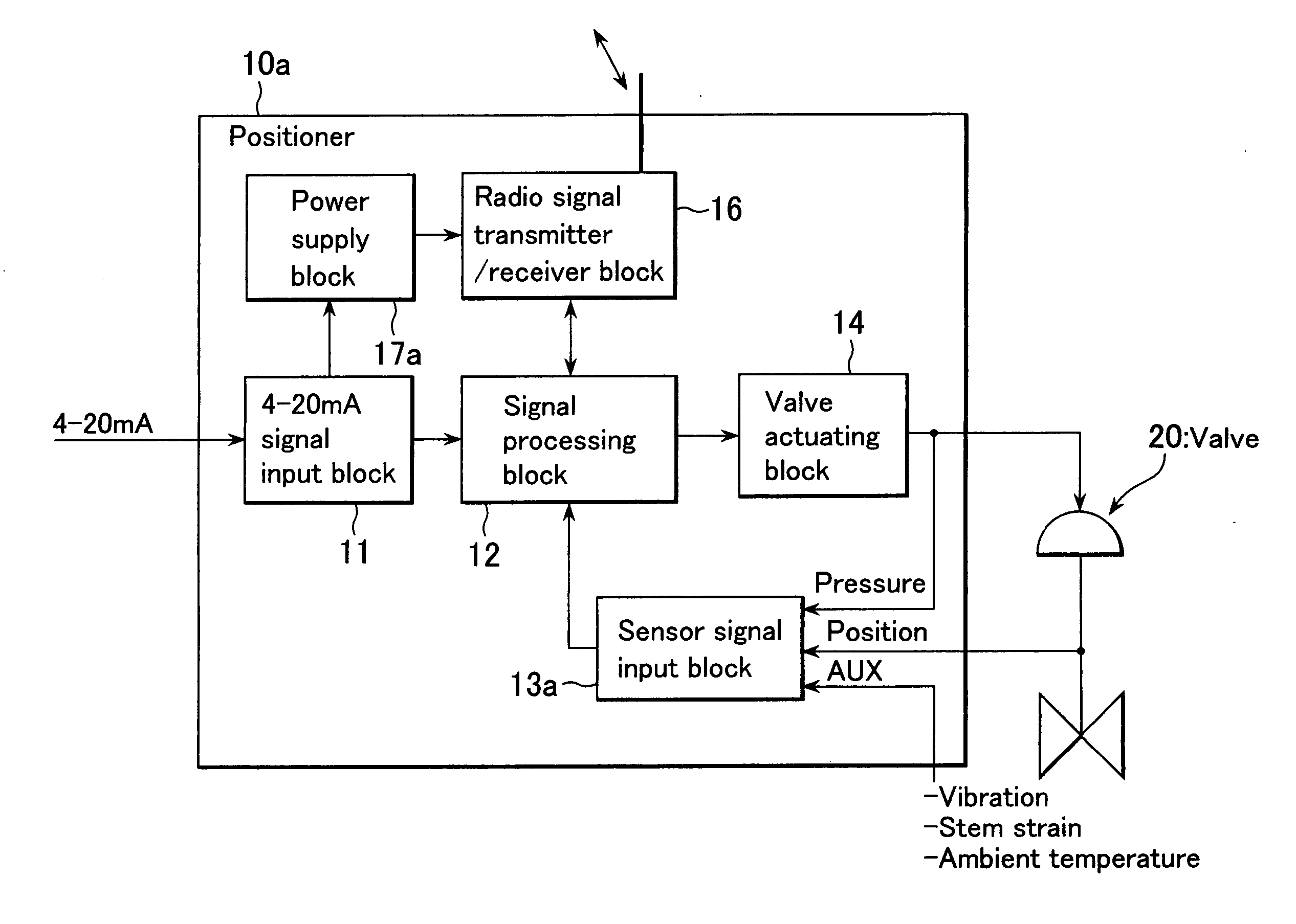
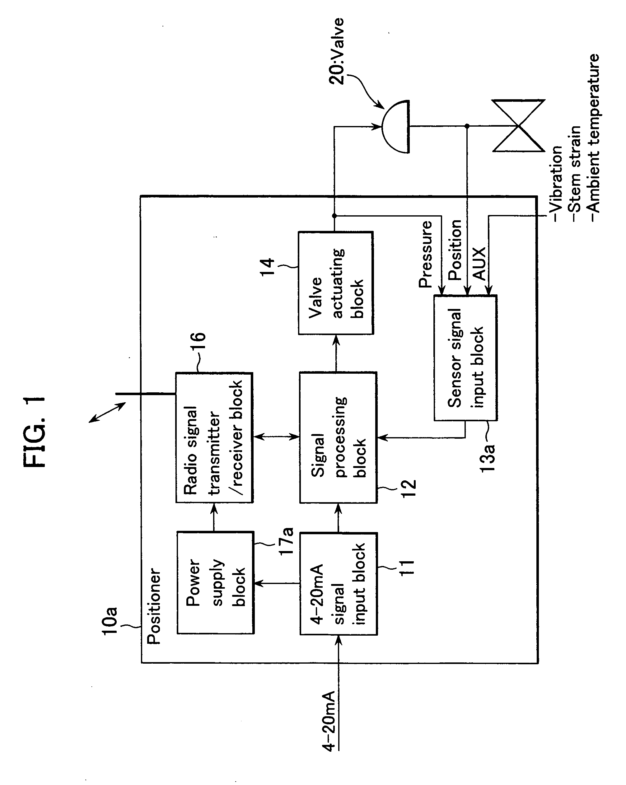
[0113] The present invention will hereinafter be described in detail with reference to FIG. 6. FIG. 6 is a block diagram illustrating a second embodiment in accordance with the present invention. Note that elements identical to those of FIG. 1 are referenced alike and excluded from the explanation.

[0114] The embodiment illustrated in FIG. 6 is characteristic in that charging circuit 41 and electric storage device 43 are used to configure the circuit. This embodiment is of valve positioner 40 (field device), and connection points A and B are connected to a signal line (not shown in the figure) through which a 4-20 mA signal (analog signal) is input.

[0115] One end of shunt regulator 31 (supply voltage generation means) is connected to connection point A and one end of current-sensing resistor 32 is connected to connection point B. In addition, the other ends of shunt regulator 31 and current-sensing resistor 32 are connected to each other at connection point E. Then, connection point...

third embodiment

[0141] The present invention will hereinafter be described in detail with reference to FIG. 7. FIG. 7 is a block diagram illustrating the valve positioner in accordance with the present invention. Note that elements identical to those shown in FIG. 6 are referenced alike and excluded from the explanation.

[0142] The embodiment (valve positioner 50) illustrated in FIG. 7 is characteristic in that like the embodiment illustrated in FIG. 6, charging circuit 51 and electric storage device 53 are used to configure the valve positioner. The embodiment illustrated in FIG. 7 is also characteristic in that the valve positioner is equipped with first shunt regulator (supply voltage generation means) 55 and second shunt regulator 56.

[0143] One end of first shunt regulator 55 is connected to connection point A. The other end of first shunt regulator 55 is connected to one end of second shunt regulator 56 at connection point N. In addition, the other end of second shunt regulator 56 is connected...

fourth embodiment

[0154] The present invention will hereinafter be described in detail with reference to FIG. 8. FIG. 8 is a block diagram illustrating the valve positioner in accordance with the present invention. Note that elements identical to those shown in FIG. 7 are referenced alike and excluded from the explanation.

[0155] The embodiment (valve positioner 60) illustrated in FIG. 8 is characteristic in that like the embodiment illustrated in FIG. 7, charging circuit 61 and electric storage device 53 are used to configure the valve positioner. The embodiment illustrated in FIG. 8 is also characteristic in that the valve positioner is equipped with charge control circuit (charge control means) 62 formed using hardware other than signal processing circuit 34.

[0156] Charge control circuit 62 is connected to connection points A and N. In addition, signal P from the output of first shunt regulator 55 is input to charge control circuit 62. Symbol P denotes a signal correlated with the electric current...


PUM


Abstract

The present invention provides a field device whereby the device's additional information can be transmitted wirelessly without the need for battery replacement or external wiring. The present invention also provides a field device whereby the firmware of a wireless module in the field device can be developed at minimum cost and whereby it can be made easy to link the firmware to applications, such as an asset management system, on the host system side. The field device in accordance with the present invention is installed in a plant, factory, or the like, connected to a higher-order distributed control system through a signal line, configured to input or output 4-20 mA signals, and comprised of: an RF unit for transmitting or receiving radio signals; and a power supply block for accumulating extra electric currents when the block is neither transmitting nor receiving radio signals; wherein electric currents accumulated in the power supply block are supplied to the RF unit so as to be used as electric power for transmitting or receiving radio signals.

Description

BACKGROUND OF THE INVENTION [0001] 1. Field of the Invention [0002] The present invention relates to a field device, such as pressure and differential pressure transmitters, flowmeters, thermometers, and valve positioners, that are arranged in a plant in a decentralized manner. More specifically, the invention relates to the improvement of a field device and a signal transfer method for wirelessly transmitting additional information, including diagnostic information held by the field device, to a system that controls the field device. [0003] 2. Description of the Prior Art [0004] In general, field devices are arranged at the location of petrochemical, food, pharmaceutical, water supply / sewerage, iron-making, or other process piping; where they detect physical quantities, including temperature, pressure and flow rate inside the piping; and transmit the detected signals to control equipment installed at a distant location or receive signals transmitted from the control equipment. Such...

Claims


Application Information

Patent Timeline
Patent Type & Authority Applications(United States)
IPC IPC(8): G08B5/22H02J50/00H02J50/20H04Q9/00H04W4/00H04W4/38H04W52/00H04W52/02
CPCG05B19/0423G05B2219/25006G05B2219/25196G05B2219/25428G05B2219/31251H04L12/10
Inventor SAITO, YOJINISHIJIMA, TAKASHI
Owner YOKOGAWA ELECTRIC CORP
Why Eureka
Try Eureka