Image display apparatus and correction apparatus thereof

a technology of image display and correction apparatus, which is applied in the direction of television systems, instruments, color signal processing circuits, etc., can solve problems such as color difference, uniformity failure, luminance difference, etc., and achieve the effect of suppressing a necessary memory, reducing the storage capacity of the memory, and reducing the storage capacity

Inactive Publication Date: 2006-05-04
CANON KK
View PDF14 Cites 29 Cited by
  • Summary
  • Abstract
  • Description
  • Claims
  • Application Information

AI Technical Summary

Benefits of technology

[0033] According to the second aspect of the present invention, it is unnecessary to hold all of necessary correction data on all pixels needed to be corrected in the first memory at a time. According to this second aspect of the present invention, the compressed correction data (compressed data) read from the second memory is extended to a part of the correction data so as to rewrite the data of the first memory. It is thereby possible to suppress a necessary memory from being made large in size. Further, according to the second aspect of the present invention, the correction circuit includes the first memory and the second memory to hold the correction data within the image display apparatus. By doing so, even if the compressed data is used for reducing a storage capacity of the memory, the unevenness of brightness or color in the pixels can be corrected without decreasing a processing rate. Further, even a display apparatus in which both the unevenness of brightness and the unevenness of color are correct simultaneously can be practiced without difficulty.

Problems solved by technology

Namely, as a display area of a projector is recently made larger in size, there occurs a uniformity failure such as a luminance difference or a color difference on the screen resulting from characteristic differences in a light source, an optical system, and a liquid crystal display device serving as an image display device that constitute the apparatus.

Method used


Image

  • Image display apparatus and correction apparatus thereof
  • Image display apparatus and correction apparatus thereof
  • Image display apparatus and correction apparatus thereof

Examples


first embodiment

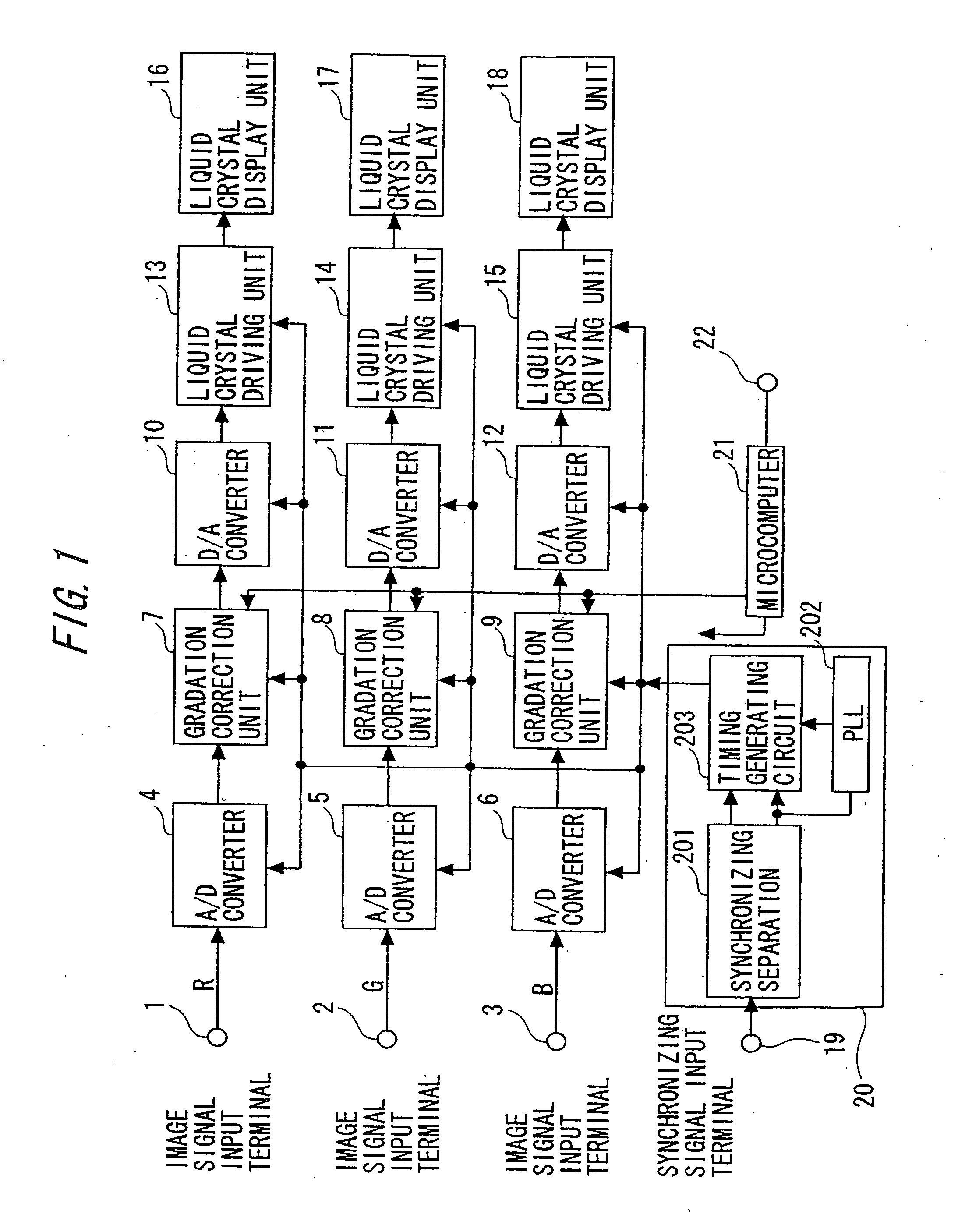
[0065] An image display apparatus according to a first embodiment of the present invention will be described. FIG. 1 is a block diagram of the image display apparatus according to the first embodiment.

[0066] As shown in FIG. 1, the image display apparatus according to this first embodiment includes image signal input terminals 1, 2, and 3 in which primary color image signals of red (R), green (G), and blue (B) are input, respectively, AD converters 4, 5, and 6, gradation correction units 7, 8, and 9, DA converters 10, 11, and 12, liquid crystal driving units 13, 14, and 15, liquid crystal display units 16, 17, and 18, a synchronizing signal input terminal 19, a microcomputer unit 21, and a timing signal generating unit 20 that includes a sync separation circuit 201, a PLL circuit 202, and a timing signal generating circuit 203.

[0067] The primary color image signals of red (R), green (G), and blue (B) are input to the respective image signal input terminals 1, 2, and 3. These prima...

second embodiment

[0184] A display apparatus according to a second embodiment of the present invention will be described. The display apparatus according to the second embodiment is basically equal in entire configuration for the signal processing shown in FIG. 1 according to the first embodiment except for a configuration and an operation of the gradation correction units 7, 8, and 9. The number of display pixels in the display unit of the display apparatus according to the second embodiment is 1920 pixels in the horizontal direction and 1080 lines (pixels) in the vertical direction. If the display apparatus is a 3-LCD projector, the number of pixels of each of the display units of the respective liquid crystal displays is equally 1920 pixels in the horizontal direction and 1080 lines (pixels) in the vertical direction.

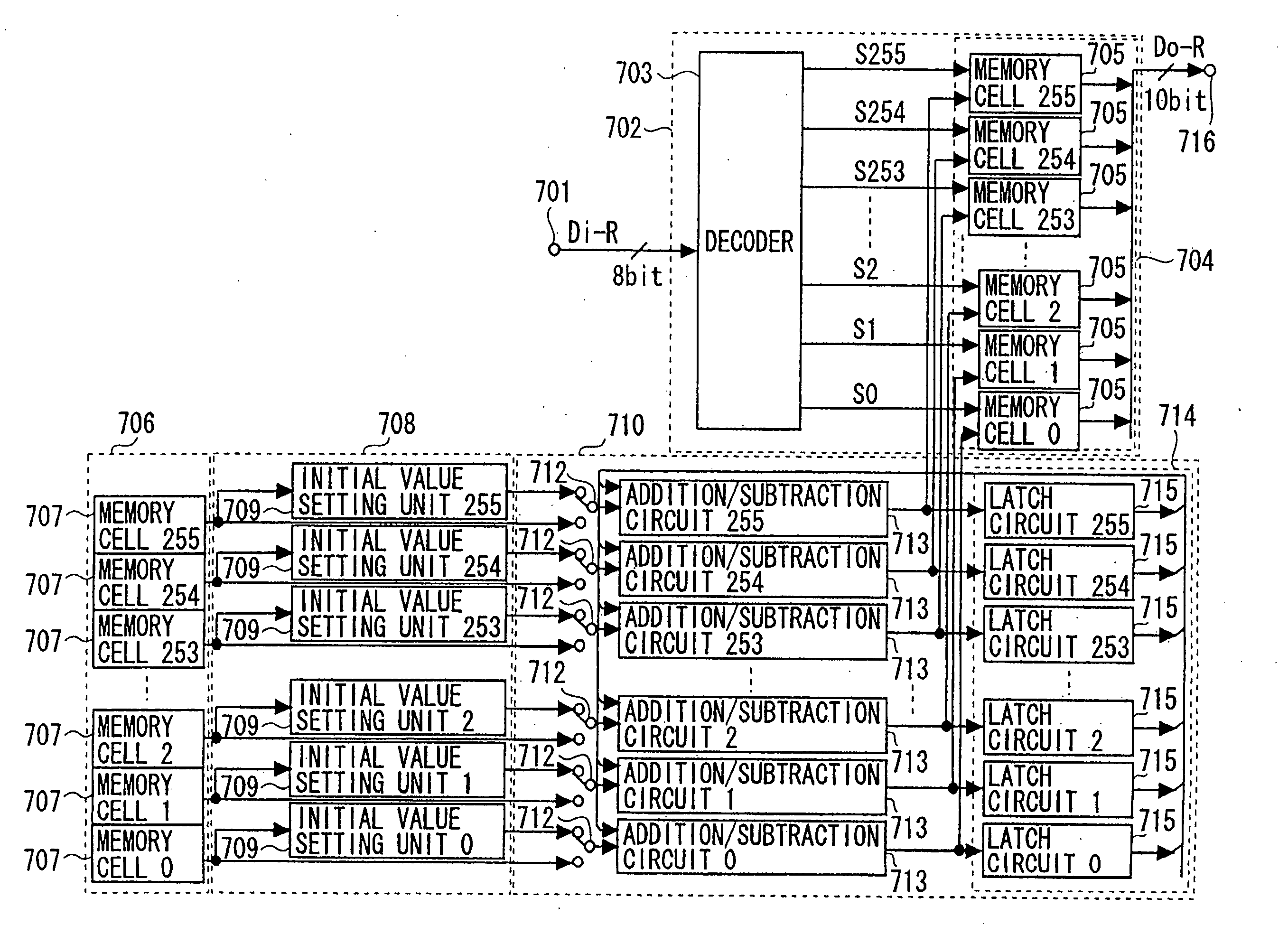
[0185]FIG. 8 depicts a red signal gradation correction unit according to this second embodiment. As shown in FIG. 8, the red image signal input unit 701 is an input unit through whic...

third embodiment

[0328] A display apparatus according to a third embodiment of the present invention will be described. The third embodiment is equal to the second embodiment except for the operation for writing display correction data to the second LUT unit 706. Only the different respects will be, therefore, described herein.

(Operation for Writing Display Correction Data to Second LUT Unit)

[0329] Namely, as for the operation for writing the display correction data to the second LUT unit 706 according to the first and the second embodiments, the memory that constitutes the second LUT unit 706 is one of the ROM, the EEPROM, the EPROM, the one time ROM, the flash memory and the like. These memories are classified as nonvolatile memories.

[0330] The data is written to the memory based on the operation performed by the PC in the data format to be described later. In this third embodiment, an additional nonvolatile memory is provided so that a third LUT unit 23 serving as a third memory is provided a...


PUM


Abstract

An image display apparatus for correcting an unevenness of brightness or color in a plurality of pixels in a display unit, comprising: a correction circuit that corrects the unevenness of brightness or color in the pixels by correcting an image input signal using correction data for correcting the unevenness in the pixels of the display unit, wherein said correction circuit includes: a first memory that holds the correction data; a second memory that holds compressed data obtained by compressing the correction data; and an operation unit that performs a processing for sequentially extending the compressed data for every part of the compressed data based on the compressed data read from the second memory, to provide the correction data on a part of corresponding pixels to be corrected, wherein the correction data held in the first memory is sequentially rewritten for the every part of the correction data by the operation unit.

Description

BACKGROUND OF THE INVENTION [0001] 1. Field of the Invention [0002] The present invention relates to an image display apparatus and a correction apparatus of an image display apparatus. The present invention is adapted particularly suitably to an image display apparatus capable of improving so-called display screen uniformity such as gradation characteristics, a luminance difference, and a color difference on a display screen, that is, capable of improving a luminance difference or a brightness difference in every pixel. [0003] 2. Description of the Related Art [0004] In recent years, as a display screen is made larger in size, various display devices such as a CRT projector, a liquid crystal projector, a plasma display, and a liquid crystal display as well as a conventional CRT direct viewing television have entered the market. These image display apparatuses are required to have high-level luminance and chromaticity uniformity on a screen according to purposes. [0005] A three-LCD ...

Claims


Application Information

Patent Timeline
Patent Type & Authority Applications(United States)
IPC IPC(8): H04N17/02H04N9/12
CPCH04N5/57H04N9/30H04N9/31H04N9/3105H04N21/4318H04N9/3194H04N9/3197H04N9/68H04N2005/745H04N9/3182
Inventor NOJI, MINORU
Owner CANON KK
Why Eureka
Try Eureka