
Polishing machine

a technology of polishing machine and polishing tape, which is applied in the direction of edge grinding machine, grinding machine components, manufacturing tools, etc., can solve the problems of slow etching rate, low throughput, and ineffective use of the whole surface of the polishing tape for polishing, so as to improve efficiency

Active Publication Date: 2006-05-04
NIHON MICRO COATING
View PDF4 Cites 33 Cited by
  • Summary
  • Abstract
  • Description
  • Claims
  • Application Information

AI Technical Summary

Benefits of technology

[0012] It is another object of this invention to provide such a polishing machine which does not cause any secondary contamination due to the polishing tape that is used.
[0022] Since a polishing machine of this invention uses a polishing tape for the polishing, there is no problem associated with machines for chemical mechanical polishing such as resistance against chemicals. Moreover, since the pad is made to move outward so as to push the polishing tape outward for contacting the target object to be polished, the polishing tape need not be bent to any extreme degree. Since the polishing head is caused to undergo reciprocating motion while the polishing tape and the target object remain in contact with each other, the whole surface of the polishing tape is made to contribute to the polishing for improved efficiency.

Problems solved by technology

By a method of removing a film by etching, on the other hand, there are situations where the etching rate becomes very slow such that the throughput becomes lower, depending on the kind of the film.
If such a polishing tape is bent excessively, the polishing layer comes to be separated and this generates particles and causes contamination.
If a polishing tape is bent in this manner as it is contacted to the edge portion of a semiconductor wafer, furthermore, it nearly becomes a point contact and the whole surface of the polishing tape cannot be effectively used for the polishing.
Polishing machines of the type not using any polishing tapes are adapted to use a dedicated special polishing material for removing a film at beveled and edge parts of semiconductor wafers and they have very complicated structures.
Although they are adapted to rotatably support a semiconductor wafer, they cannot move in the perpendicular direction and hence cannot be used for polishing edge portions.

Method used


Image

  • Polishing machine
  • Polishing machine
  • Polishing machine

Examples


Embodiment Construction

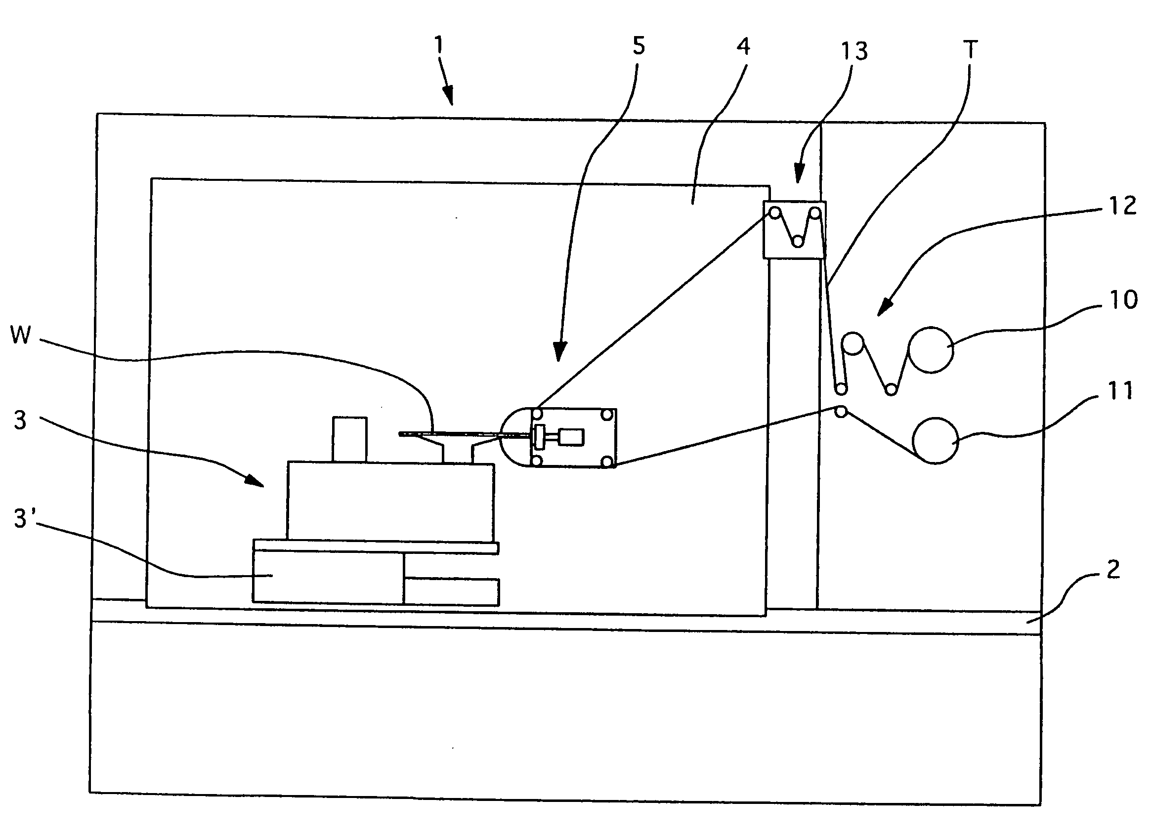
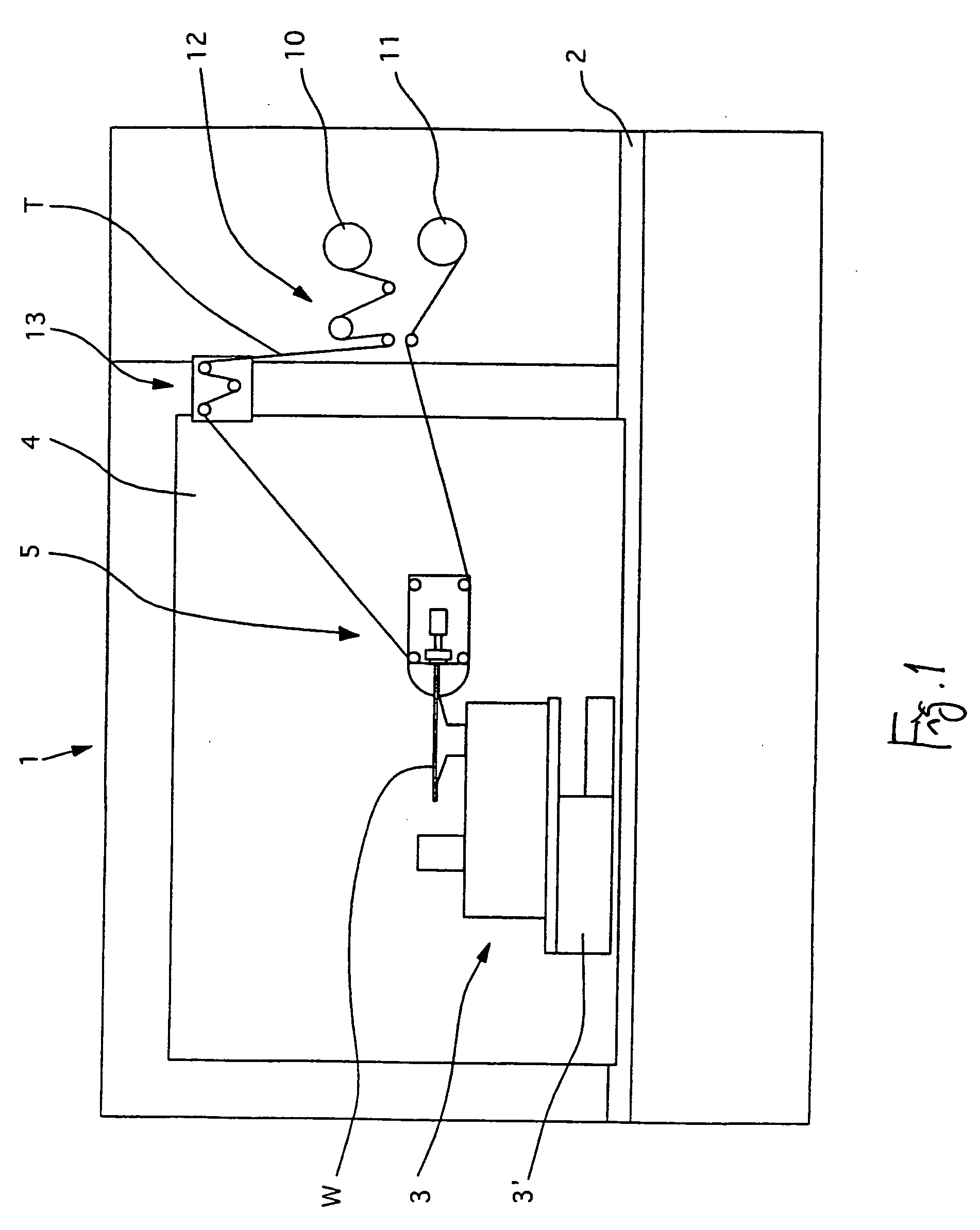
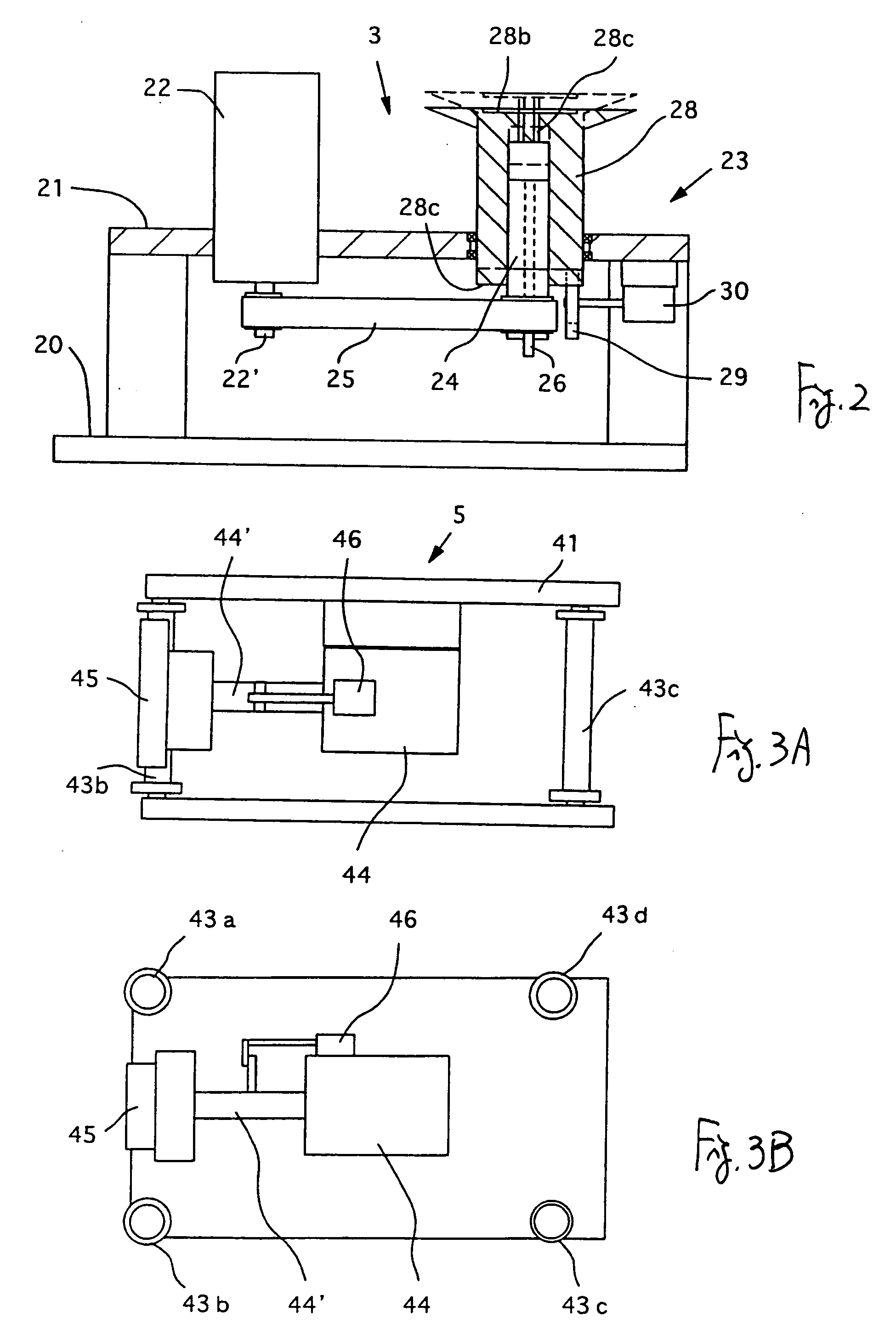
[0034]FIG. 1 schematically shows a polishing machine 1 embodying this invention, having a moving device 3 on a horizontal table plate 2 for moving a target body W to be polished vertically, rotationally and horizontally, as will be explained more in detail below. A front plate 4 provided with a polishing head 5 is attached perpendicularly to the table plate 2. If necessary, pipes for supplying water that is required for the polishing and chemicals that may be used for chemical mechanical polishing may be attached to the front plate 4.

[0035] A supply roller 10 for supplying a polishing tape T and a take-up roller 11 for winding up the polishing tape are provided to another plate disposed at a side of the table plate 2. In addition, a feed roller 12 and an auxiliary roller 13 are provided. The feed roller 12 is for transporting the polishing tape T at a fixed speed. The auxiliary roller 13 is for preventing the polishing tape T from experiencing any excessively large stress as the po...


PUM


Abstract

A polishing machine uses a polishing head having a movable pad to press a polishing tape for polishing beveled and edge parts of a disk-shaped object. A rotary shaft is connected to the polishing head in a direction of contact surface between the polishing tape and the object. A rotary-and-reciprocating motion device rotates the polishing head around the axial line of the rotary shaft and moves it reciprocatingly along its axial line. A moving device undergoes a reciprocating motion perpendicularly to the object surface while supporting the object. When in use, the polishing head is rotated while the pad causes the polishing tape to protrude from it while the object is rotated.

Description

[0001] This application is a continuation of International Application No. PCT / JP2005 / 007436, filed Apr. 19, 2005 which claims priority on Japanese Patent Application 2004-124696 filed Apr. 20, 2004.BACKGROUND OF THE INVENTION [0002] This invention relates to a polishing machine for polishing edges and portions near the edges of a target object by using a polishing tape and more particularly to such a polishing machine adapted to carry out the polishing by contacting the polishing tape to the target object without bending the polishing tape more than necessary. [0003] A thin film is formed as shown in FIG. 10A on the surface of a target object to be polished such as a semiconductor wafer (indicated by letter W) but it is something to be removed because the thin film at beveled portions (indicated by letter B) along an edge or that on an edge section (indicated by letter E) on a circumference inside such a beveled portion tends to be a source of particles or contaminations of other f...

Claims


Application Information

Patent Timeline
IPC IPC(8): B24B21/00B24B41/04B24B9/00B24B9/06H01L21/304
CPCB24B21/002B24B9/065B24B9/00B24B21/00H01L21/304
Inventor SATO, SATORUTAMURA, JUNWATANABE, JUN
Owner NIHON MICRO COATING
Learn More