Toroidal rotary damper apparatus

a rotary damper and rotary damper technology, which is applied in the direction of shock absorbers, liquid based dampers, mechanical instruments, etc., can solve the problems of limited dynamic range, inherent characteristics of traditional van type rotary dampers, frictional losses, etc., and achieve excellent sealing properties, low internal static pressure, and reduce internal friction and hysteresis

Inactive Publication Date: 2006-05-11
MORADIAN NORICK B
View PDF7 Cites 22 Cited by
  • Summary
  • Abstract
  • Description
  • Claims
  • Application Information

AI Technical Summary

Benefits of technology

[0013] The present invention relates to a toroidal rotary damper apparatus which has a number of advantages over prior art damper constructions. The toroidal rotary damper apparatus has excellent sealing properties due to constant contact between a piston employed in the apparatus and the interior of a toroidal shaped housing. Due to symmetrical geometry of the piston and the surrounding arcous interior, the piston or the shaft seals do not require a pre-load force, this considerably reduces internal friction and hysteresis. The apparatus has a low internal static pressure and has a constant internal volume, eliminating the need for a high pressure gas chamber or secondary expansion chamber to compensate for an external rod.

Problems solved by technology

Traditional van type rotary dampers have inherent disadvantages, including the following:
Hysteresis, due to disproportionate vane and shaft seal pre-load; caused by means such as compression springs, Elastomers, band springs or Elastomer Composites, resulting in frictional losses and limited dynamic range;
A rotary vane damper housing is subject to hoop stress, compression deformation and bending strain at vane junctions, causing excessive bypass flow and subsequent loss of compression; and
Thermal hysteresis due to non-uniform coefficient of expansion; exasperated by long sealing contours of the vane and structural components, leading to unpredictable sealing properties at higher temperatures and friction at lower temperatures.
This limits the operating temperature range and diminishes the damping characteristics during thermal cycles.
Furthermore, such prior art devices are hampered by their relative complexity, weight and high cost.
All of the above measures reduce damping efficiency, add cost, complexity and weight as well as require substantial space.
Since telescopic dampers, to conform to non-linear elasto-kinematics motion of the associate elements, are deployed predominantly with translational mechanisms, they can not be installed directly, or fixedly to a haul or a chassis.
This curtails the thermal conductance capacity of the damper and of the fluid.
Also, conventional translational or linear dampers have limitations when applied to long travel functions.
It is difficult to accommodate a large travel due to the danger of bucking the damper shaft, especially at high relative velocities, the linear space claim required by the length of a linear damper can also create packaging problems.
Functionally, in order to achieve the desired damper force-velocity characteristics, it is very difficult to adjust the piston-valve; solutions such as a hollow piston rod containing an internal shaft that performs the adjustments being very costly and often incompatible with servo controls due to high torque demands.
Piston embedded servo valves are also complex, as well as reducing the hydraulic capacity of the damper.

Method used


Image

  • Toroidal rotary damper apparatus
  • Toroidal rotary damper apparatus
  • Toroidal rotary damper apparatus

Examples


Embodiment Construction

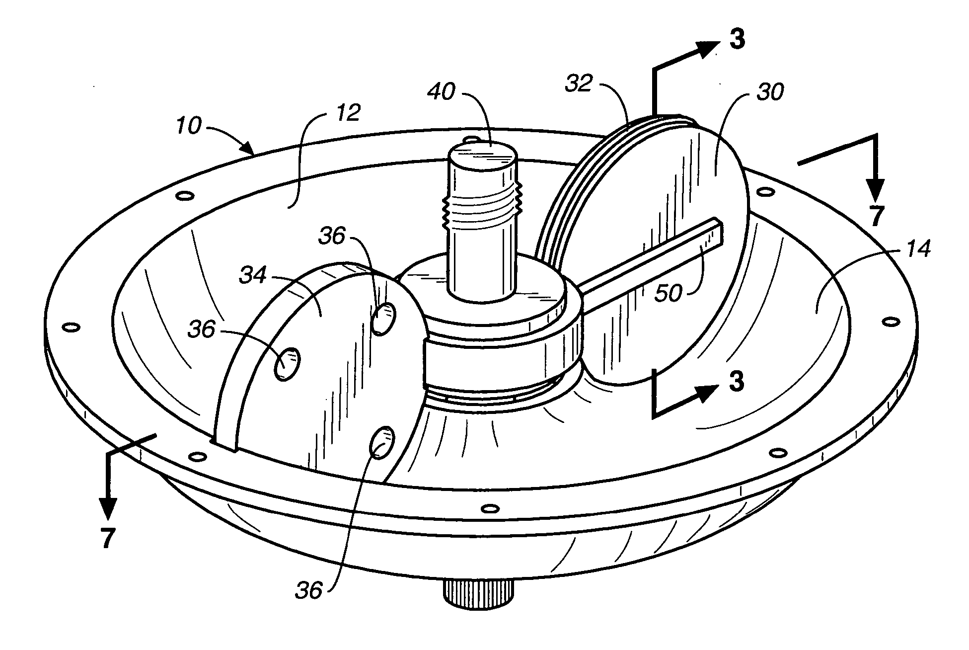
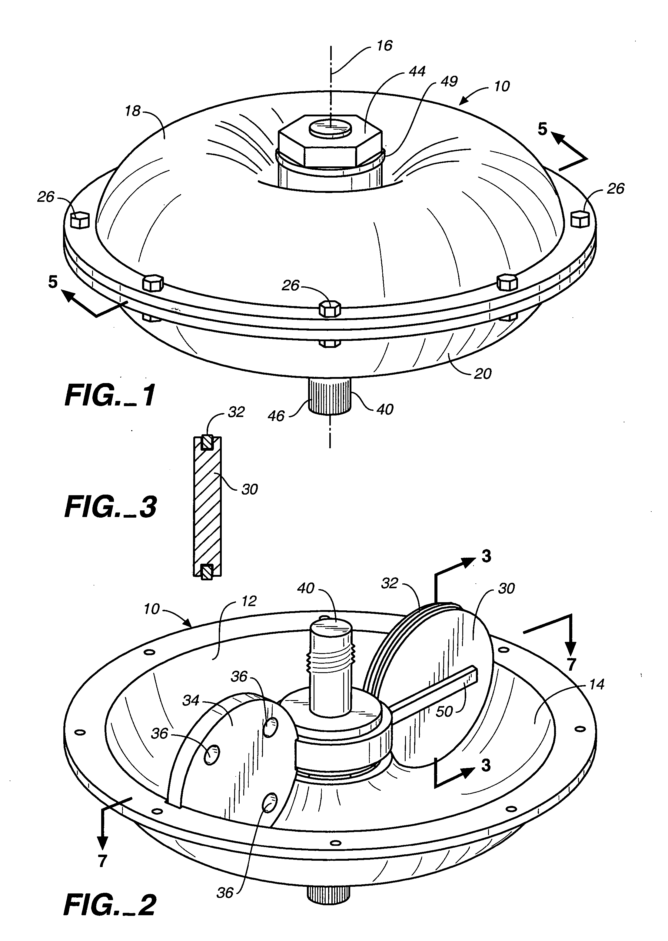
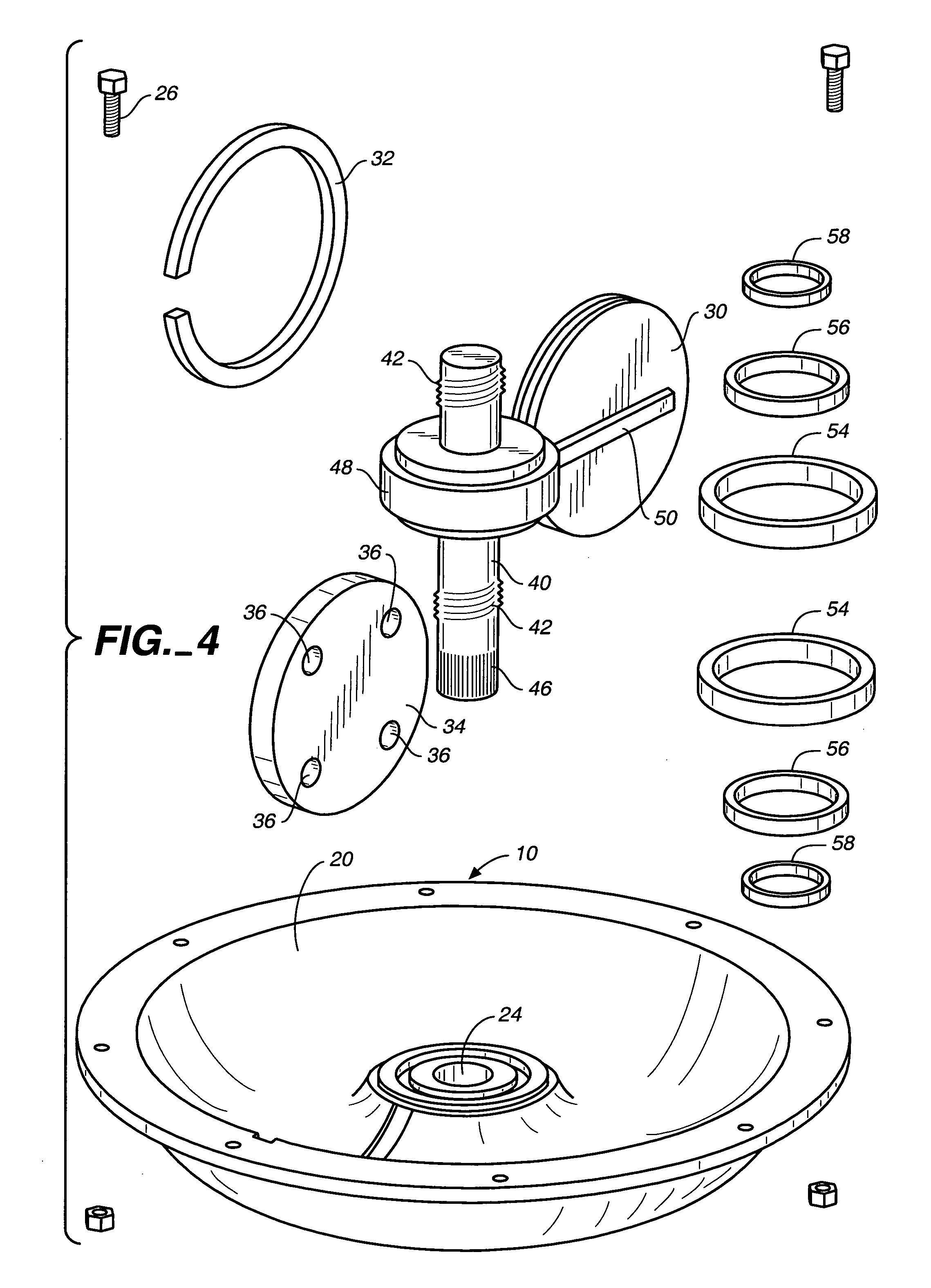
[0049] Referring now to FIGS. 1-6, a toroidal rotary damper apparatus constructed in accordance with the teachings of the present invention is illustrated. The apparatus includes a housing 10 defining a housing interior 12 for containing damper fluid (not shown) of any conventional nature. The housing interior has a substantially circular cross section and is formed by a toroidal inner housing surface 14 disposed about and spaced from a central axis 16.

[0050] The housing 10 includes two adjoining housing members 18, 20, each housing member defining a portion of the housing interior and further defining openings 22, 24, respectively, at the centers thereof. Threaded fasteners 26 extending through holes in outer flanges of the housing members are utilized to releasably secure the housing members together.

[0051] A piston 30 having a substantially circular-shaped outer peripheral piston surface at which is located an outer seal 32 is in substantially fluid-tight, slidable engagement w...


PUM


Abstract

A toroidal rotary damper apparatus includes a housing having a toroidal inner housing surface and a piston moveable in the housing having a curved outer peripheral piston surface in engagement with the inner housing surface. A fluid barrier is attached to the housing and located in the housing interior. A flow control passageway defined by either the piston or the fluid barrier controls passage of damper fluid when there is relative rotational movement between the piston and the housing to dampen the forces causing relative rotational movement.

Description

TECHNICAL FIELD [0001] This invention relates to damper apparatus for dampening a force, for example a force caused by relative movement between two structural elements operatively associated with the damper apparatus. BACKGROUND OF THE INVENTION [0002] Dampers are hydraulic devices used to restrict the number of cyclic oscillations caused by a deflection force; damping forces are generated by pumping fluid through regulating orifices, converting kinetic energy into laminar and turbulent friction. Two types of damping devices are currently in wide use; telescopic and rotary vane type. Traditional van type rotary dampers have inherent disadvantages, including the following: [0003] 1. Hysteresis, due to disproportionate vane and shaft seal pre-load; caused by means such as compression springs, Elastomers, band springs or Elastomer Composites, resulting in frictional losses and limited dynamic range; [0004] 2. A rotary vane damper housing is subject to hoop stress, compression deformat...

Claims


Application Information

Patent Timeline
Patent Type & Authority Applications(United States)
IPC IPC(8): F16F9/14
CPCF16F9/145
Inventor MORADIAN, NORICK B.
Owner MORADIAN NORICK B
Why Eureka
Try Eureka