Active vibration damping device

a technology of active vibration and damping device, which is applied in the direction of shock absorbers, machine supports, mechanical equipment, etc., can solve the problems of damage to the device itself, inability to maintain continuous operation in a high frequency range, and inability to reliably guarantee the durability and reliability of operation, etc., to achieve excellent sliding

Inactive Publication Date: 2006-05-11
SUMITOMO RIKO CO LTD
View PDF5 Cites 15 Cited by
  • Summary
  • Abstract
  • Description
  • Claims
  • Application Information

AI Technical Summary

Benefits of technology

[0038] According to this mode, the axis-perpendicular direction displacement permitting assembly of the fourth mode can be realized advantageously. In this mode, attachment of the connecting rod to the movable element positioned in the axial direction while permitting displacement thereof in the axis-perpendicular direction may be advantageously achieved, for example, by sandwiching the movable element in the axial direction by a pair of abutting members with excellent slidability, fitted externally onto the connecting rod, and elastically positioning the abutting members with respect to the connecting rod by means of a biasing rubber part or the like, while utilizing the urging force of the biasing rubber part to press the pair of abutting members against the movable element. In this sort of arrangement, displacement of the connecting rod relative to the movable element in the axis-perpendicular di

Problems solved by technology

In the event that a solenoid actuator of this kind is to be employed, for example, in an automotive engine mount or other vibration damping device, there is a problem in that the actuator, and hence the vibration damping device itself, may not readily afford satisfactory durability and reliability with regard to operating performance.
This is due to the fact that, while in the case of an automotive engine mount, it is necessary for the device to be able to provide continuous vibration damping for a predetermined time period in a high frequency range of several tens of Hz and above for an extended time of several years or more, a typical solenoid actuator cannot consistently maintain such continuous operation in a high frequency range for an extended period.
However, since the interval between the movable element and the guide hole consists of a very small gap all the way around, it is difficult to avoid the movable element coming into contact with the inside face of the guide hole, due to error in component tolerances and assembly, or change of parts over time.
Particularly in vibration damping devices such as those discussed above, even if the actuator by itself is a high precision component, it is nevertheless extremely difficult to maintain a high degree of accuracy of relative position of the stator and the movable element while installed in the vibration damping device, so contact of the movable element with the inside face of the guide hole is unavoidable in actual practice.
The reason for this lies in the fact that vibrat

Method used


Image

  • Active vibration damping device
  • Active vibration damping device
  • Active vibration damping device

Examples


first embodiment

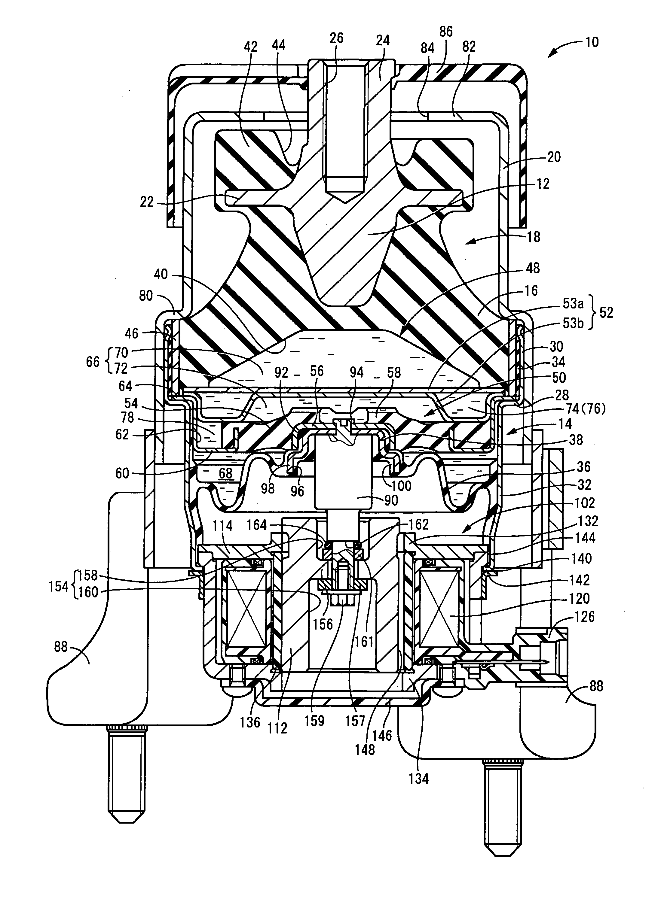
[0054] Referring first to FIG. 1, there is shown an active vibration damping device in the form of an automotive engine mount 10 of construction according to the present invention. The arrangement of this engine mount 10 has a mount body 18 composed of a metallic first mounting member 12, and a metallic second mounting member 14, positioned in opposition and spaced apart from one another, and elastically linked by means of a main rubber elastic body 16 interposed between them; and installed fitting within a stopper fitting 20 of metal. With the first mounting member 12 attached to a power unit (not shown) and the second mounting member 14 attached to an automobile body (not shown), the power unit is supported on the body in a vibration-damped manner. In this installed state, the distributed load of the power unit is exerted on the engine mount 10, across the first mounting member 12 and the second mounting member 14 in the mounting center axis direction, which is the vertical direct...

second embodiment

[0093] Referring next to FIG. 5 and FIG. 6, an electromagnetic oscillator 180 serving as the solenoid actuator is shown as a component of an active vibration damping device of construction according to the invention. The electromagnetic oscillator 180 has an upper groove 184 and a lower groove 186 as magnetism biasing mechanis, formed over part of the circumference of the armature 182. Specifically, in this electromagnetic oscillator 180, by means of forming upper and lower grooves 184, 186 in the armature 182, the zones permitting passage of lines of magnetic force differ along the circumference of the armature 182. It is possible thereby to vary in the circumferential direction the number of lines of magnetic force flowing through the armature 182, to generate in one direction in the circumferential direction, a resultant force of the magnetic force components acting in the axis-perpendicular direction. The specific shapes of the upper and lower grooves 184, 186 are not limited in...

third embodiment

[0094] Referring next to FIG. 7 and FIG. 8, an electromagnetic oscillator 200 serving as the solenoid actuator is shown as a component of an active vibration damping device of construction according to the invention, wherein wide diameter portions 210, 212 of large diameter dimension are formed overlapping in the circumferential direction, in through-holes 206, 208 bored through the centers of the upper yoke 202 and the lower yoke 204 which form the magnetic path. The armature 214 in this electromagnetic oscillator 200 is of generally tubular shape. By means of this design, the distance between the armature 214 and the magnetic poles 132, 134 formed in the wide diameter portions 210, 212 is greater, and the magnetic force acting on the armature 214 can be made to vary in the circumferential direction. According to this embodiment, there is no change in weight balance due to furnishing the armature 214 with a notch or groove, nor is there any change in outside diameter dimension, so ...


PUM


Abstract

An active vibration damping device wherein first and second mounting members are linked by a main rubber elastic body, a pressure receiving chamber having a non-compressible fluid sealed therein is defined by the main rubber elastic body at one part and by an oscillation member in the other part. A solenoid actuator designed with a movable element positioned inserted into a guide hole of a stator having a yoke member is attached about a coil to form a stator-side magnetic path with the guide hole lying on its center axis, so that current passed through the coil creates actuating force in the axial direction between the stator and the movable element. The stator of the solenoid actuator is affixed to the second mounting portion and the movable element is attached to the oscillation member. A bias urging assembly is disposed for urging the movable element in one axis-perpendicular direction to the stator.

Description

INCORPORATED BY REFERENCE [0001] The disclosure of Japanese Patent Application No. 2004-328190 filed on Nov. 11, 2004 including the specification, drawings and abstract is incorporated herein by reference in its entirety. BACKGROUND OF THE INVENTION [0002] 1. Field of the Invention [0003] The present invention relates to an active vibration damping device for use as an automotive engine mount, body mount, or the like in order to produce active or countervailing damping action of vibration to be damped, and relates in particular to an active vibration damping device adapted to provide active vibration damping action by means of employing an oscillation member to constitute part of the wall of a pressure receiving chamber with a non-compressible fluid sealed therein, and controlling pressure within the pressure receiving chamber by means of exciting actuation of the oscillation member with a solenoid type actuator. [0004] 2. Description of the Related Art [0005] Fluid filled type acti...

Claims


Application Information

Patent Timeline
IPC IPC(8): F16F13/00F16F15/00
CPCF16F13/101F16F13/264
Inventor WATANABE, YOSHINORI
Owner SUMITOMO RIKO CO LTD
Why Eureka
Try Eureka