[0031] It is an object of the present invention to provide methods and apparatus for increased efficiency, adaptability, economy and versatility in a multi-
sensor system for the benefit of visually impaired and blind people in finding their way to a specific target.
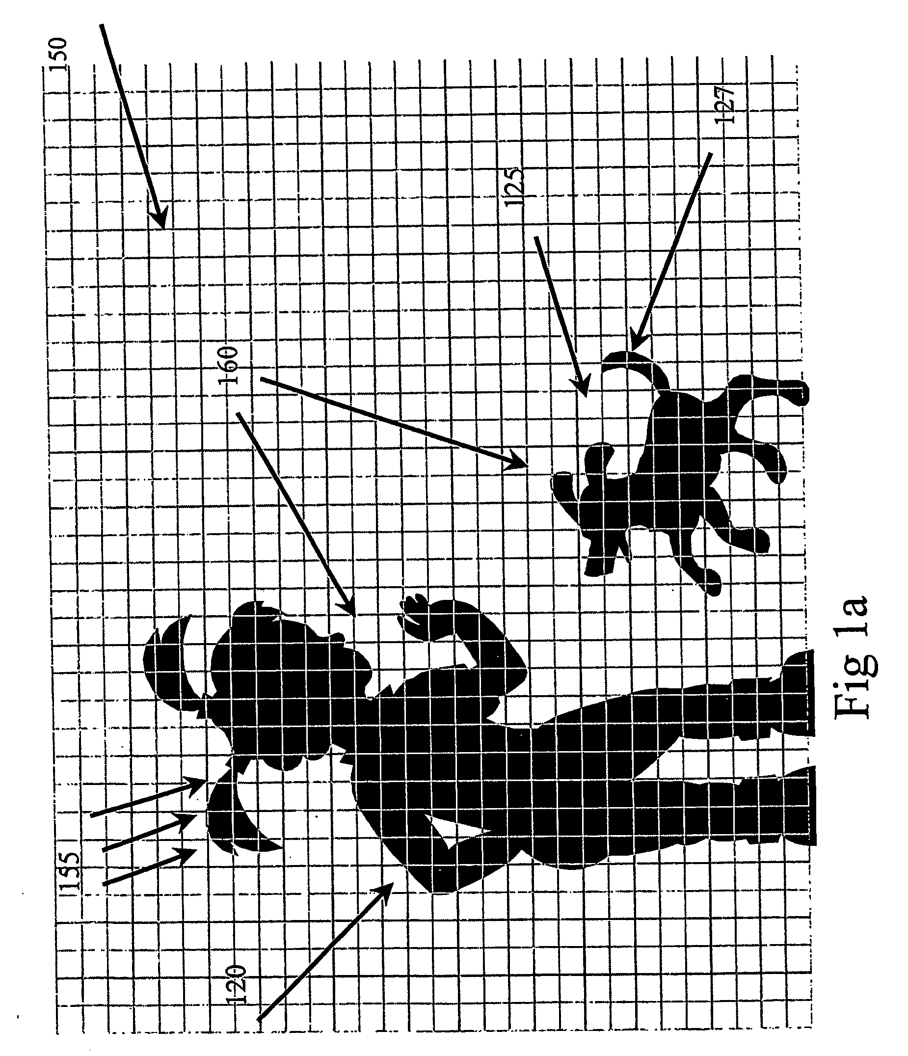
[0033] It is a still further object of the present invention to provide methods and apparatus to enable the creation of an overall mental picture of the surrounding physical environment of a visually impaired or blind person, and to enhance communication concerning the environment.
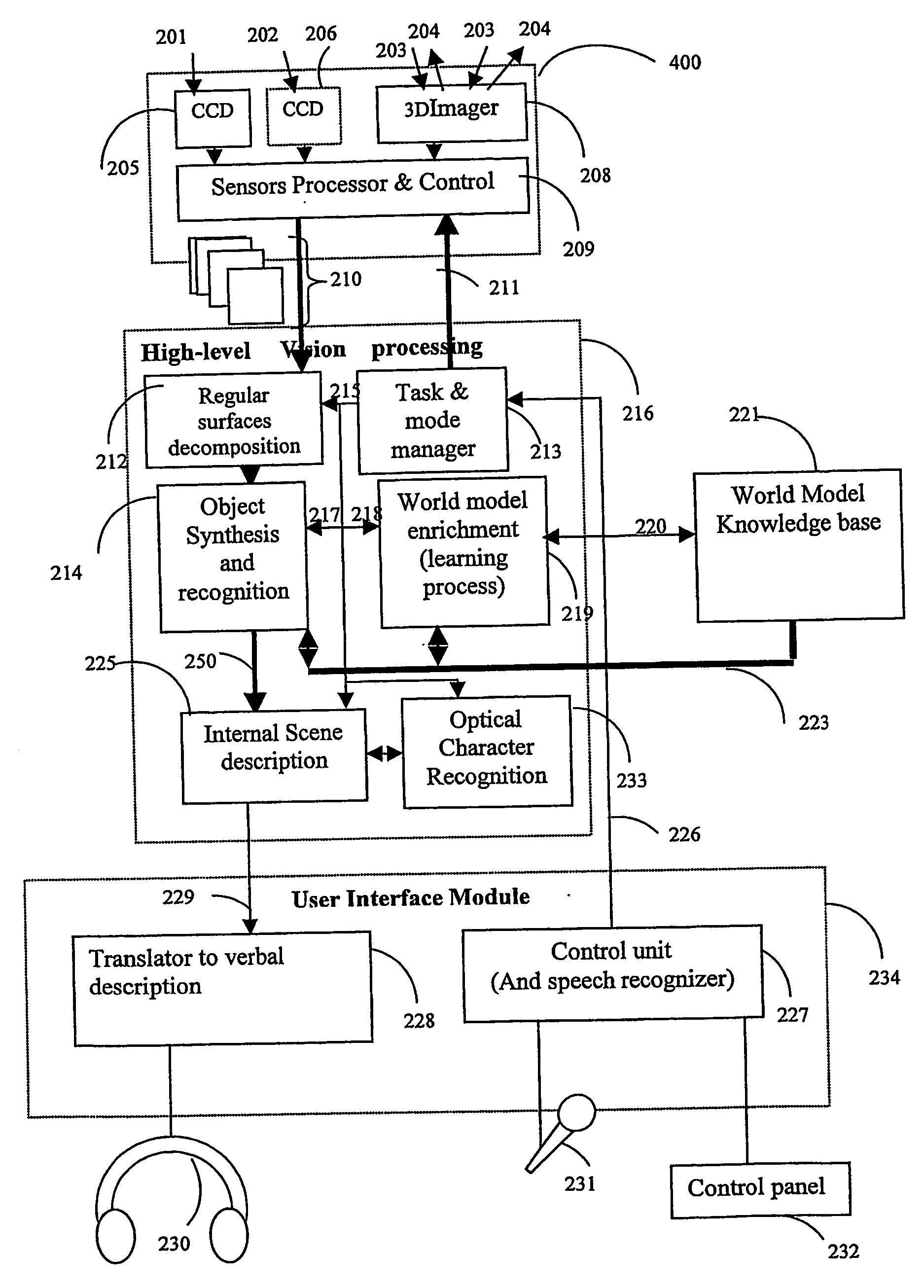
[0034] An apparatus and method are described for aiding a visually impaired or blind person to detect, identify and avoid objects in the field of vision of the surroundings. The apparatus includes electro-optical devices to detect and identify objects, a
control unit, which receives and processes information from the devices and a vocal representation unit to receive instructions from the control unit for the purpose of audibly describing the objects to the person in the field of vision, thereby enabling the person to cope and proceed safely in the surroundings. The method describes the aid for a visually impaired person to detect, identify and avoid objects in the field of vision surroundings, including the steps of receiving visual images of the objects, receiving range information concerning the objects,
processing the image information and audibly describing to the person the objects in the field of vision, thereby enabling the person to cope with, and proceed in his surroundings.
[0035] These objects, and others not specified hereinabove, are achieved by an exemplary embodiment of the present invention, wherein the
system of the present invention is designed to aid visually impaired or blind pople to detect, identify and avoid obstacles on their way and assist in finding their way to a specific target. The integration of two sensors, a 3D
laser imaging sensor and a computerized
vision sensor, create an overall
mental image of the surrounding physical environment. The system of the present invention is compact and light weight, and can be mounted on head of the blind person.
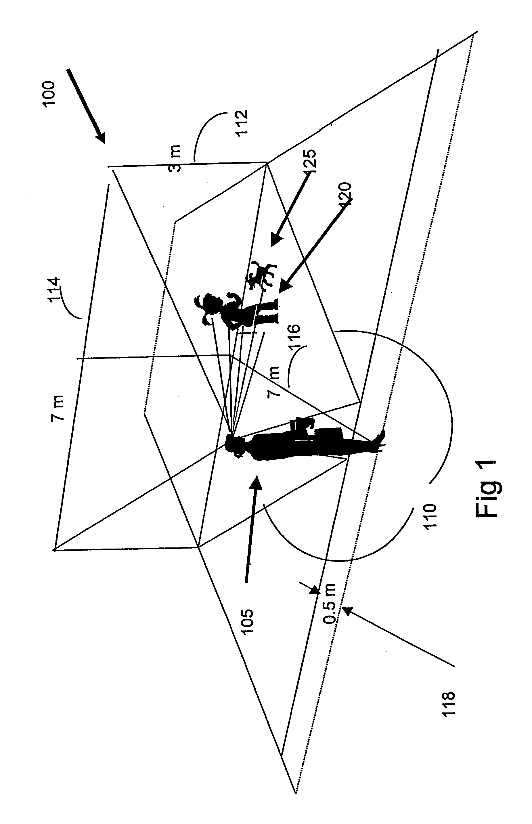
[0036] The system of the present invention provides detection and identification of fixed or moving obstacles, and can provide estimates of the relative range, speed and bearings of several simultaneous obstacles and objects. The system of the present invention alerts the blind person of immediate danger and provides the needed information by synthesized voice.
[0037] The system of the present invention has small physical dimensions, allowing the user
free movement. Object identification and description is provided for a range up to 20 meters, as well as alerts for potential
close range obstacles between one and two meters away, including stationary and moving objects, and changes in
ground level, for example, steps or a ramp. The system gives estimates of the relative speed of objects, such as “moving fast towards you,” or “moving away”, etc. A continuous verbal scene description is provided according to the relevance and level of
threat. The system of the present invention has the ability to “concentrate” on a specific object in order to achieve a higher level of details, and has the ability to read signs. A capability to “learn” is built in, thereby continually adding to the stored environment model with new objects, relevant details and description methods.

