Illuminator for video display apparatus

a video display and illumination technology, applied in the field of illumination, can solve the problems of high operating temperature, poor color gamut, uv-ir problems, etc., and achieve the effects of increasing the total light output of the video display apparatus, enhancing optical efficacy and system brightness, and increasing brightness

Inactive Publication Date: 2006-05-11
GLOBAL FIBEROPTICS
View PDF7 Cites 25 Cited by
  • Summary
  • Abstract
  • Description
  • Claims
  • Application Information

AI Technical Summary

Benefits of technology

[0045] Since light emitted from the light panel of the illuminator of the present invention irradiates upon the SLM uniformly, the total light output of the video display apparatus can be increased by augmenting the electric current or by increasing the number of solid-state ligh

Problems solved by technology

Although these kinds of lamps exhibit high luminance, they have disadvantages which include high power consumption, high operating temperature, poor color gamut, UV-IR issues, volatile glass bulb construction, sizable mass and volume, longer switch time, short lifespan, higher costs, and, due to the use of mercury, and not being environmentally friendly.
Therefore, these kinds of lamps are only used when high luminance is required.
The built in coated reflective surface and special lens shaped structures are costly to manufacture and are difficult to align which in turn could lead to a lack of uniformity in performance from one LED to the next.
Although the projector exerts good uniformity, it lacks compactness and is heavily weighted.
Furthermore, the separation and recombination of color light beam that occurs when the color light beams emitted from the three separate LED sources pass through the DXP could result in lateral color smearing in the projection image.
The latter would be due to the color light beam's having a large incident angle and consequently reflecting repeatedly within the columnar light leading member and not being able to leave.
This would result in a lowered system luminous flux output.
Furthermore, because each small-plane light source must be accompanied by its own light leading member, the system becomes large in size and costly to manufacture as well as hard to align in the production line.
The three-laser projection display has limitations on th

Method used


Image

  • Illuminator for video display apparatus
  • Illuminator for video display apparatus
  • Illuminator for video display apparatus

Examples


Embodiment Construction

[0074] As shown in the drawings for purpose of illustration, the present invention is embodied in several different types of illuminators and light modules and can be applied to video display apparatuses and other applications.

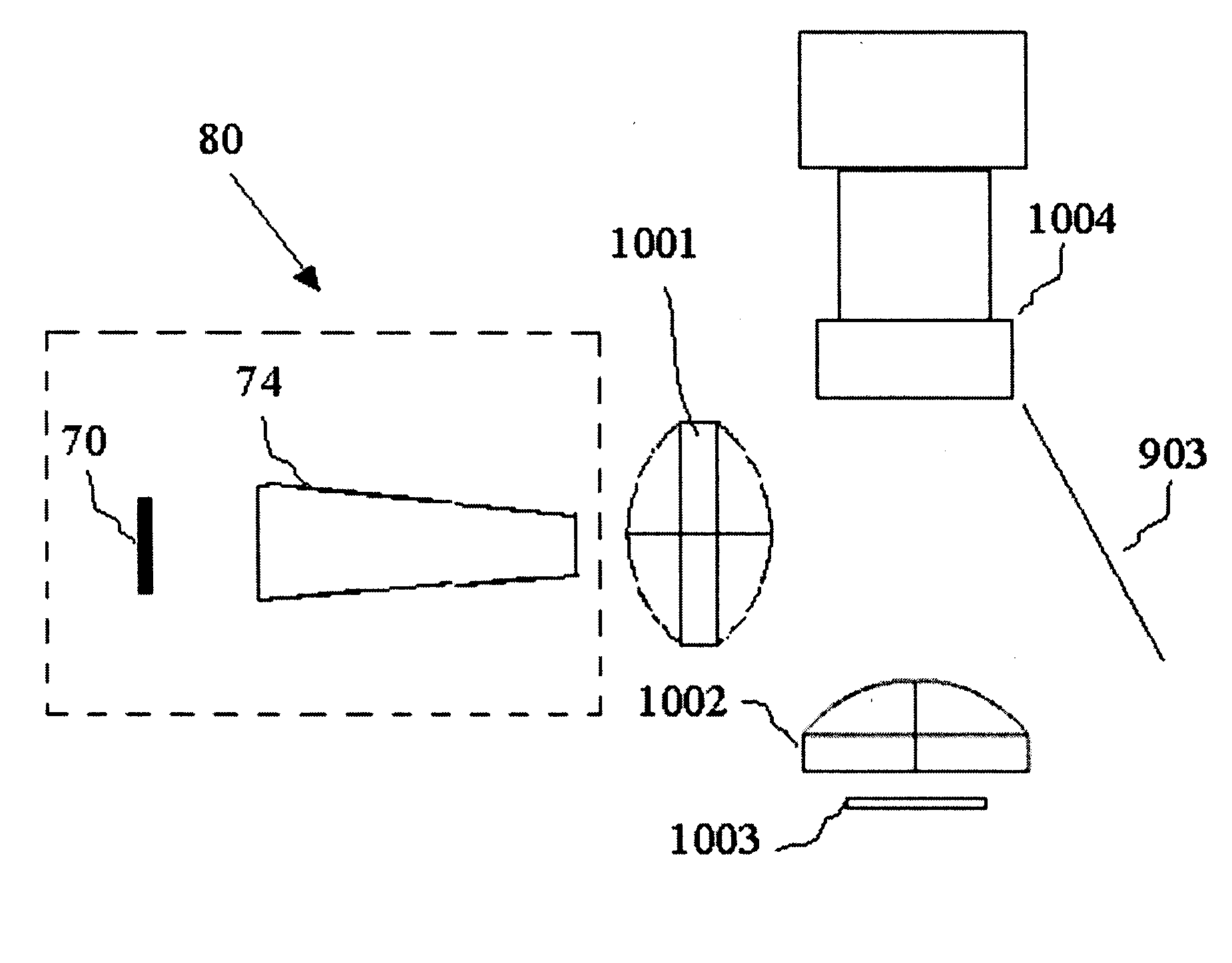
[0075] The present invention illustrates different kinds of illuminators. An illuminator comprises at least a light panel and an integrator. The examples of illuminators, marked as illuminator 80, are shown in FIG. 8. FIG. 8 shows an illuminator 80 which comprises a light panel 70 and an integrator 74. The light panel 70 shown in FIG. 7 comprises at least one solid-state lighting unit 701 but commonly comprises a profuse number of solid-state lighting units 701.

[0076] The light beams emitted from the solid-state lighting units 701 are more directional than those of conventional LEDs. Therefore, there is no focus, diffusive optical element, and / or external reflection optical element, which collimate or condense the light emitted from the solid-state lighting ...


PUM


Abstract

The present invention relates to an illuminator that comprises one or a plurality of light panels which further comprise highly directional solid-state lighting units, wherein the light component emitted from the highly directional solid-state lighting unit has high directivity, and a light panel comprising an array of the highly directional solid-state lighting units need no additional optical elements to collimate or condense the light emitted from the light panel. The present invention also relates to the applications thereof in video display apparatuses, rear projection televisions, printers, scanners, copy machines, and more. The present invention realizes a uniform high luminous solid-state color source and video display apparatus of compact size that exhibits high utilized efficiency of a luminous flux from the light panel source and can provide a uniform image. The present invention can be used in general lighting, automobile lighting and other display systems. Its compactness, high optical utilized efficiency, brightness and uniformity, low cost design and ability to project a still or moving picture with high color reproduction capabilities make it useful in the applications described above.

Description

BACKGROUND OF THE INVENTION [0001] 1. Field of the Invention [0002] The present invention relates to an illuminator that comprise one or a plurality of light panels which further comprise highly directional solid-state lighting units, wherein the light panel comprising an array of the highly directional solid-state lighting units needs no additional optical elements to collimate or condense the light emitted from the light panel. The present invention also relates to the applications thereof in video display apparatuses, rear projection televisions, printers, scanners, copy machines, and more. [0003] 2. Description of the Related Art [0004] A conventional projection apparatus is typically applied to a front projection lens or a large screen. Light sources such as halogen lamps and arc lamps with high luminance have to be used. Although these kinds of lamps exhibit high luminance, they have disadvantages which include high power consumption, high operating temperature, poor color gam...

Claims


Application Information

Patent Timeline
IPC IPC(8): H01L33/00F21V7/04
CPCG02F1/1336H04N9/3152H04N9/3164H04N9/3197
Inventor HSU, CHIH-LUHUNG, CHUN-CHANGLEE, JEFFREY
Owner GLOBAL FIBEROPTICS
Why Eureka
Try Eureka