Sighting device and additional device for measuring, working, and/or operating with or without contact

Inactive Publication Date: 2006-05-11
OPTRIS
View PDF15 Cites 8 Cited by
  • Summary
  • Abstract
  • Description
  • Claims
  • Application Information

AI Technical Summary

Benefits of technology

[0007] An objective of the present invention is to specify a sighting device, as well as a device with a measuring, working, and/or operating device which can be used with or without contact, of the type stated initially in which on the one hand

Problems solved by technology

In so doing however, a series of problems arises.
Due to the special processing of the infrared-optical materials the introduction of central holes in the objective is relatively expensive.
The structural elements for measurement center sighting reduce the effective aperture of the infrared measurement channel due to their size.
In addition

Method used


Image

  • Sighting device and additional device for measuring, working, and/or operating with or without contact
  • Sighting device and additional device for measuring, working, and/or operating with or without contact
  • Sighting device and additional device for measuring, working, and/or operating with or without contact

Examples


Embodiment Construction

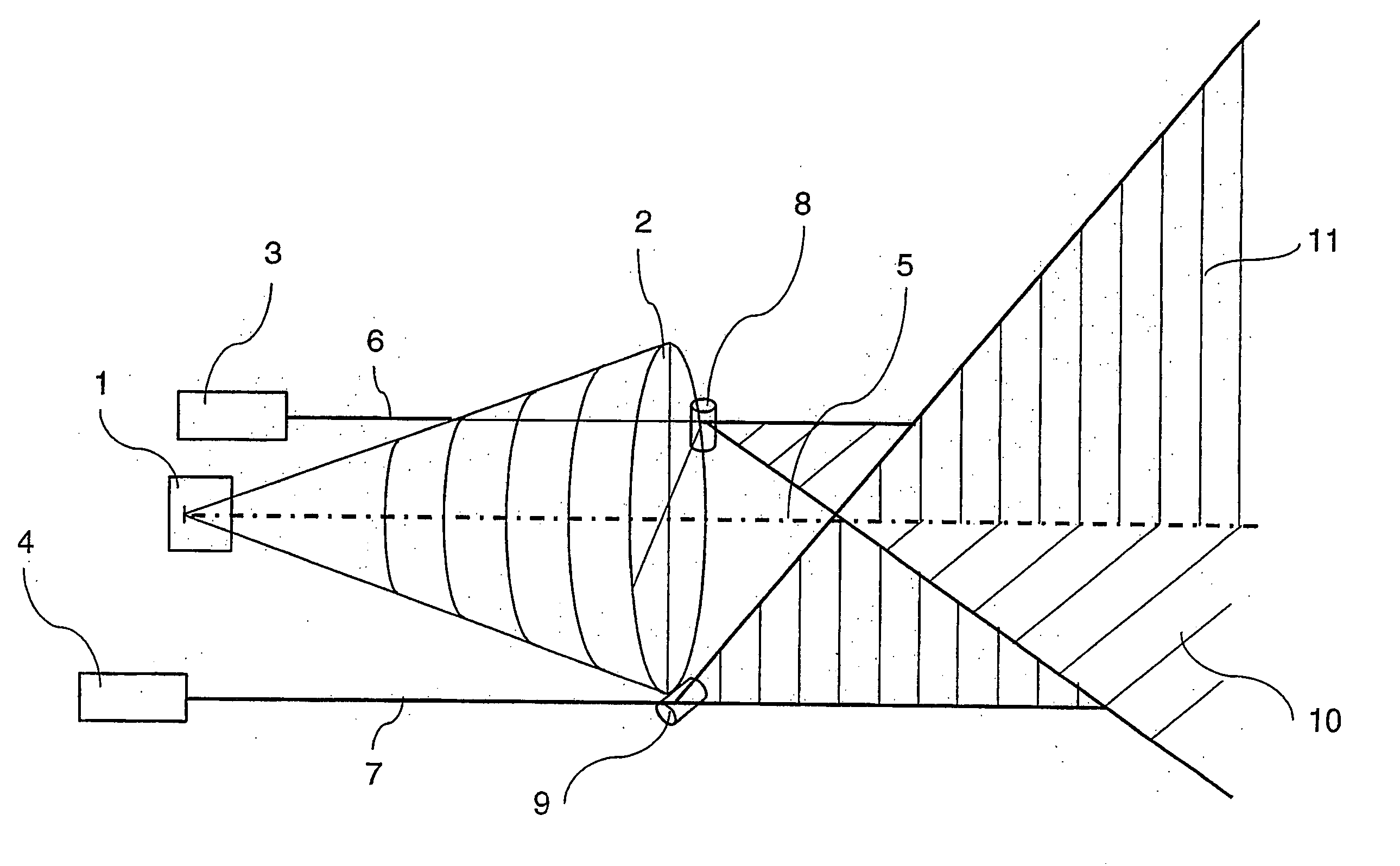
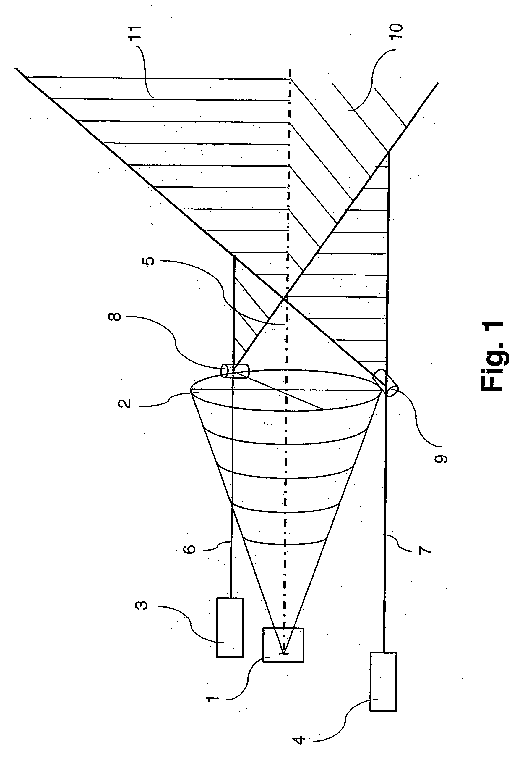
[0040]FIG. 1 shows in a schematic side view a first embodiment example of a device according to the invention with a measuring device which can be used without contact and works interactively with an object of any type at a predetermined target location, where the target location's position can be fixed by means of a sighting device. The device comprises a detector 1 on which the electromagnetic radiation originating from a measured spot on an object not represented can be imaged by means of a lens 2.

[0041] The sighting device includes two lasers 3, 4 which are disposed to the side of the optical axis 5 of the detector 1. The lasers 3, 4 generate two sighting rays 6, 7 which run parallel to the optical axis 5 of the detector 1 and strike two optical components 8, 9 disposed on the outer circumferential surface of the lens 2. The first laser 3 and the associated optical component 8 are located, according to the perspective representation in FIG. 1, behind the optical axis 5 while th...


PUM


Abstract

A sighting device is provided which is used to produce an optically perceptible target marking on an object. The sighting device includes one or more light sources for providing at least two sighting rays. A precision target marking is produced in such a manner that each of the sighting rays is directed onto a respective optical component enabling both of the sighting rays to be split on a respective illumination plane in such a manner that at least two illumination planes intersect at an angle. The point of intersection forms the target marking. A measuring, working and/or operating device is optionally provided which can be used with or without contact and which interacts with an object of any type at a predetermined target location. The target location can be detected by means of the inventive sighting device.

Description

CROSS-REFERENCE TO RELATED APPLICATIONS [0001] This application is a continuation of, and claims the benefit of priority to international PCT application number PCT / DE2004 / 001427, which was filed on Jul. 5, 2004, and which designates the United States. The disclosure of the referenced international PCT application is hereby incorporated herein by reference.FIELD OF THE INVENTION [0002] The invention relates to a sighting device for the generation of an optically perceptible target marking on an object with at least one light source to produce two sighting rays. Furthermore, the invention relates to a device with a measuring, working, and / or operating device which can be used with or without contact, where that device interacts with an object of any type at a predefined target location which can be fixed by means of the sighting device. BACKGROUND OF THE INVENTION [0003] Sighting devices and devices of the type coming into consideration here have been known in practice for a long tim...

Claims


Application Information

Patent Timeline
IPC IPC(8): G01K1/14F41G7/26G01J5/08
CPCF41G7/263G01J5/08G01J5/0803G01J5/0831G01J5/0859G01J5/089G01J5/0896G01J5/07
Inventor KIENITZ, ULRICH
Owner OPTRIS
Why Eureka
Try Eureka