Robot for use with orthopaedic inserts

a robotic and insert technology, applied in the field of robotic guidance of orthopaedic surgical procedures, can solve the problems of significantly reducing the likelihood of complications in the procedure, and achieve the effects of reducing the likelihood of complications, and convenient rendering

Active Publication Date: 2006-05-11
MAZOR ROBOTICS
View PDF17 Cites 169 Cited by
  • Summary
  • Abstract
  • Description
  • Claims
  • Application Information

AI Technical Summary

Benefits of technology

[0012] The present invention seeks to provide a new robotic guidance system, with the robot mounted directly on the bone on which the operation is being performed, or in a configuration which ensures that the robot position has a direct one-to-one relationship with the position of the bone, and which assists the orthopaedic surgeon in performing procedures involving the alignment of surgical tools with features of internally located implants utilized in the performance of the desired orthopaedic procedure. The robot itself is small, and is thus unobtrusive and easily rendered safe for use in the sterile operating room environment. The system significantly reduces the likelihood of complications arising in the procedure, since the surgical tool in use is aligned automatically with its target site, both laterally and angularly. Furthermore, the need for numerous, trial and error, X-ray fluoroscopic images is reduced, thus increasing radiation safety for all involved. The system is particularly suitable for the automatic alignment of a bone drill with predrilled holes present in metallic inserts within or in contact with the patient's bone. One preferred use of such a system is for the robotically-controlled guidance of a target drill to exactly match the position and orientation of the distal locking holes in a pre-inserted intramedullary nail, as used in long bone fracture reduction. The mounting of the robot directly on the bone, and hence also effectively on the nail, which is inserted firmly into the bone, has the advantage that if the nail rotates, the robot moves with it, thus preserving the mutual orientation and position of the guide drill with the distal holes in the nail. If the robot is alternatively mounted directly on the nail, this advantage applies directly.

Problems solved by technology

The system significantly reduces the likelihood of complications arising in the procedure, since the surgical tool in use is aligned automatically with its target site, both laterally and angularly.

Method used


Image

  • Robot for use with orthopaedic inserts
  • Robot for use with orthopaedic inserts
  • Robot for use with orthopaedic inserts

Examples


Embodiment Construction

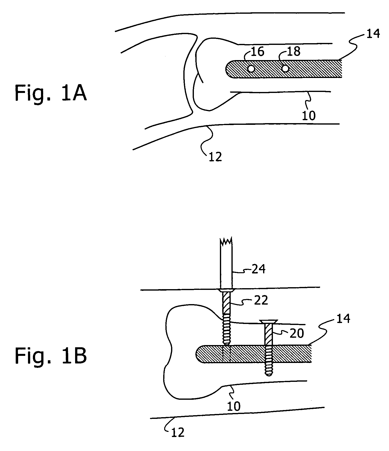
[0049] Reference is first made to FIGS. 1A and 1B, which are schematic representations of views that would be obtained by X-ray fluoroscopic imaging, illustrating the distal locking stage of the intramedullary nailing procedure. FIG. 1A is representative of a lateral image and FIG. 1B a frontal image, of the distal part of the femur 10, showing the intramedullary nail 14 with two distal locking nail holes 16, 18. The nail 14 is inserted through a minimal opening, usually in the proximal part of the bone 10, without the need to surgically expose the fracture.

[0050] In performing the procedure, the surgeon first reduces the fracture by manipulating the proximal and distal bone fragments through the leg 12 until they are aligned. The surgeon then inserts a guide wire, reams the canal if necessary, and drives in the nail 14. The surgeon then drills the appropriate distal locking nail holes in the bone, opposite the pre-prepared holes 16, 18 in the nail, and inserts lateral proximal and...


PUM


Abstract

A robot-guided system to assist orthopaedic surgeons in performing orthopaedic surgical procedures on pre-positioned inserts, including for the fixation of bone fractures, and especially for use in long bone distal intramedullary locking procedures. The system provides a mechanical guide for drilling the holes for distal screws in intramedullary nailing surgery. The drill guide is automatically positioned by the robot relative to the distal locking nail holes, using data derived from only a small number of X-ray fluoroscopic images. The system allows the performance of the locking procedure without trial and error, thus enabling the procedure to be successfully performed by less experienced surgeons, reduces exposure of patient and operating room personnel to radiation, shortens the intra-operative time, and thus reduces post-operative complications.

Description

FIELD OF THE INVENTION [0001] The present invention relates to the field of the robotic guidance of orthopaedic surgical procedures performed on pre-positioned inserts, and especially for use in the orthopaedic reduction of bone fractures using intramedullary locking procedures. BACKGROUND OF THE INVENTION [0002] The need for precise, minimally invasive, surgical interventions has resulted in the creation of methods of using computers in conjunction with advanced assistance devices to improve surgical planning and execution. Over the past decade, a variety of such Computer Integrated Surgery (CIS) systems have been developed, with resulting clinical benefits, largely for use in the fields of neurosurgery, laparoscopy, maxillofacial surgery and orthopaedics, as for instance described in the article by L. Joskowicz et al., entitled “Computers in imaging and guided surgery”, published in Computers in Science and Engineering, Vol. 3(5), pp 65-72, 2001. [0003] CIS systems can potentially...

Claims


Application Information

Patent Timeline
Patent Type & Authority Applications(United States)
IPC IPC(8): G06K9/00A61B17/17A61B17/58A61B19/00G05B19/402
CPCA61B17/1703A61B17/1721A61B17/1725A61B17/1728A61B19/201A61B19/22A61B19/2203A61B19/50A61B2019/2226A61B2019/5238G05B19/402G05B2219/39011G05B2219/40267G05B2219/45168G05B2219/49113Y10S128/922Y10S128/908Y10S128/923A61B34/70A61B17/72A61B34/10A61B34/30A61B90/11A61B2017/681A61B2034/2065A61B2034/304A61B2090/376
Inventor SHOHAM, MOSHEJOSKOWICZ, LEOMILGROM, CHARLESYANIV, ZIVSIMKIN, ARIEL
Owner MAZOR ROBOTICS
Why Eureka
Try Eureka