Compact optical transceivers including thermal distributing and electromagnetic shielding systems and methods thereof

Inactive Publication Date: 2006-05-11
IBM CORP
View PDF4 Cites 18 Cited by
  • Summary
  • Abstract
  • Description
  • Claims
  • Application Information

AI Technical Summary

Benefits of technology

[0023] Further consistent with achieving the foregoing aspects and improving on the prior art the present invention makes provisions for a optical transceiver comprising: a housing assembly including a carrier member and a heat sink cover member coupled to a portion of the carrier member to define at least a portion of an enclosure therewith; an optical subassembly including an electro-optical transmitter unit positioned within the enclosure; a retainer assembly mounted on a first end portion of the carrier member and enclosing portions of the optical subassembly; the retainer assembly including a first set of structures which, in combination, with the carrier member define at least one electrical connector port for allowing connection of an electrical connector to the optical subassembly, the retainer assembly including a second set of structures which, in combination, with the carrier member define at least one vent surrounding portions of the connector port, wherein the vent allows bidirectional passage of air therethrough, such that air can easily pass generally ove

Problems solved by technology

Not only are compactness concerns important for module design, but so are thermal management issues.
This is because transceiver modules, in operation, tend to generate relatively significant amounts of heat.
Not only do the smaller confines of a reduced sized module impact negatively on overall thermal management issues in a general sense, but such compactness places some of the module's components that operate at relatively high temperatures even closer to components that must operate at cooler temperatures, for optimal performance reasons, thereby adversely affecting the performance of the latter.
Accordingly, significant and opposing design constraints are imposed on the manufacture and reliable operation of such transceivers considering the countervailing demands for more powerful transceiver components and end user demands for module compactness satisfying industry standards.
Many known transce

Method used


Image

  • Compact optical transceivers including thermal distributing and electromagnetic shielding systems and methods thereof
  • Compact optical transceivers including thermal distributing and electromagnetic shielding systems and methods thereof
  • Compact optical transceivers including thermal distributing and electromagnetic shielding systems and methods thereof

Examples


Example

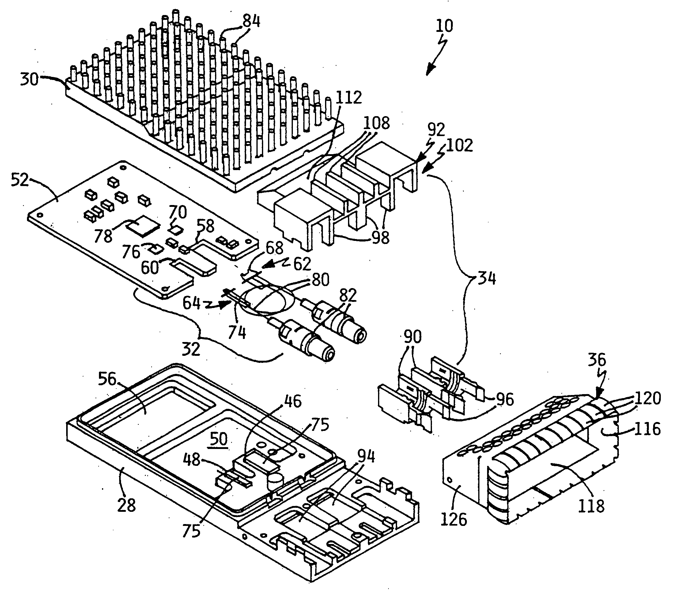
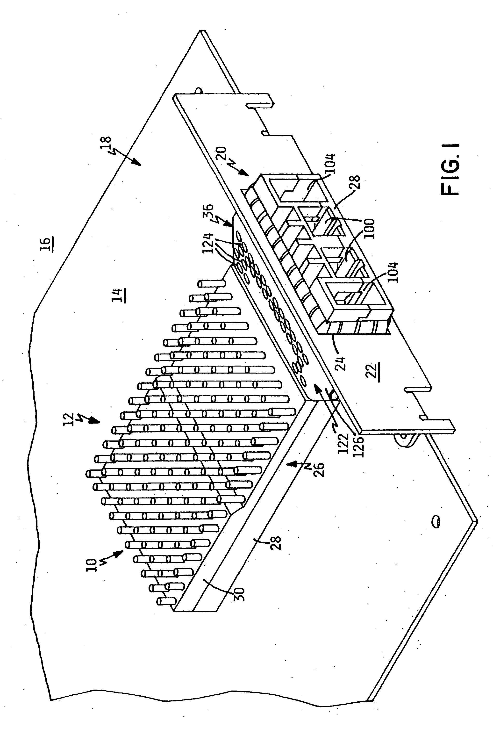
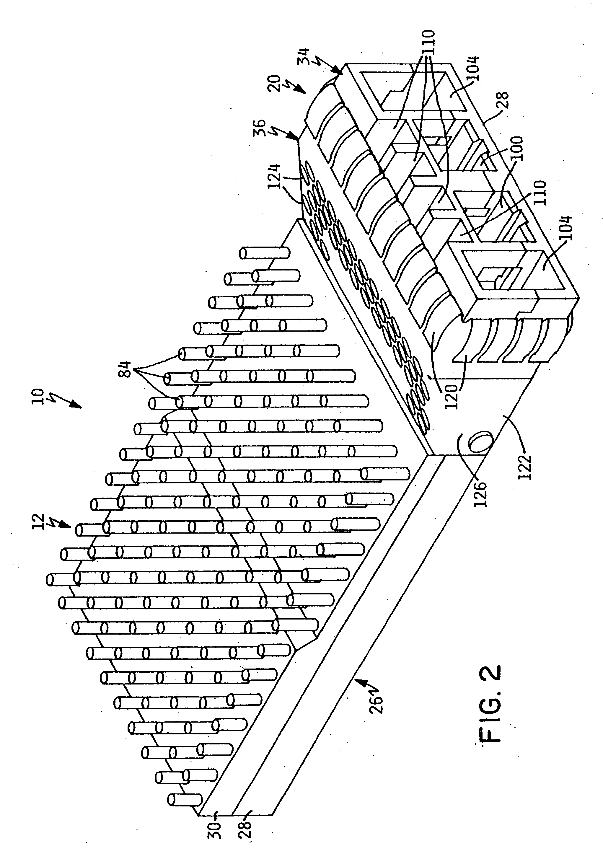
[0035]FIGS. 1-8 illustrate one preferred embodiment of an optical transceiver module made according to the principles of the present invention and designated by reference numeral 10. As illustrated in FIG. 1, the optical transceiver module 10 has a first or proximal end portion 12 mounted directly on a host circuit card 14 of a known type that is within a space 16 formed by a host data transfer system 18, such as a mid-range computer system commercially available from International Business Machines Corporation. Other types of data transfer or communication systems are contemplated for use with the transceiver module of the present invention, such as input / output devices, or other peripheral devices. The proximal end portion 12 of the optical transceiver module 10 is otherwise attached to the host card by suitable attaching elements, such as screws (not shown). A distal or connector end portion 20 of the module is releasably coupled to a system wall 22 in a manner to be described af...


PUM


Abstract

An optical transceiver includes structures that define an electrical connector port for allowing connection of an electrical connector to an optical subassembly of the transceiver, and structures that define a vent surrounding at least portions of the connector port, whereby the vent allows bidirectional passage of air therethrough. Included in the transceiver are structures that define electromagnetic interference shielding and selectively transfer heat of heat generating electronic components by conduction to a transceiver housing. Methods of cooling the transceiver by ventilation and internal heat conduction are present.

Description

REFERENCE TO PARENT APPLICATION [0001] This patent application is a divisional of the co-pending patent application “COMPACT OPTICAL TRANSCEIVERS INCLUDING THERMAL DISTRIBUTING AND ELECTROMAGNETIC SHIELDING SYSTEMS AND METHODS THEREOF”, Ser. No. 09 / 809,699 filed by Anderl et al. on Mar. 15, 2001, which is incorporated herein by reference. CROSS-REFERENCE TO RELATED APPLICATIONS [0002] The present application is related to the following commonly-assigned and copending U.S. Patent Applications: U.S. Ser. No. 09 / 809,650 entitled: AN OPTICAL FIBER COUPLER AND AN OPTICAL FIBER COUPLER INCORPORATED WITHIN A TRANSCEIVER MODULE; U.S. Ser. No. 09 / 809,531 entitled: TECHNIQUE AND APPARATUS FOR COMPENSATING FOR VARIABLE LENGTHS OF TERMINATED OPTICAL FIBERS IN CONFINED SPACES; U.S. Ser. No. 09 / 809,127 entitled: HIGH FREQUENCY MATCHING METHOD AND SILICON OPTICAL BENCH EMPLOYING HIGH FREQUENCY MATCHING NETWORKS; all filed concurrently herewith and all incorporated herein as a part hereof.BACKGROUN...

Claims


Application Information

Patent Timeline
IPC IPC(8): G02B6/36H04B10/00
CPCH04B10/806
Inventor ANDERL, WILLIAM JAMESBRANCH, SCOTT MICHAELGAIO, DAVID PETERHANLEY, MICHAEL FRANCISHOGAN, WILLIAM K.MAHANEY, HOWARD VICTOR JR.
Owner IBM CORP
Why Eureka
Try Eureka