Hoop stress relief mechanism for gas turbine engines

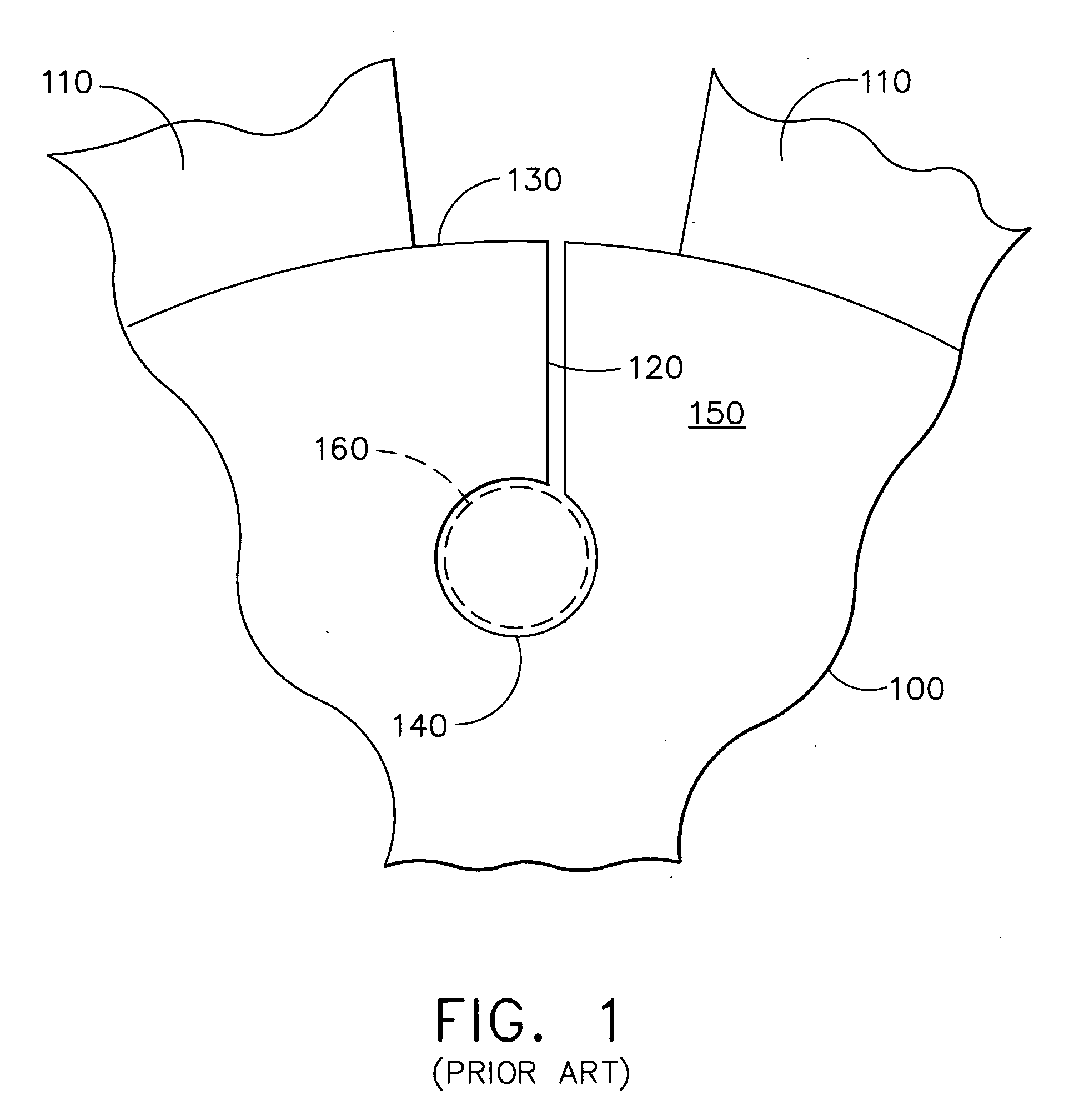
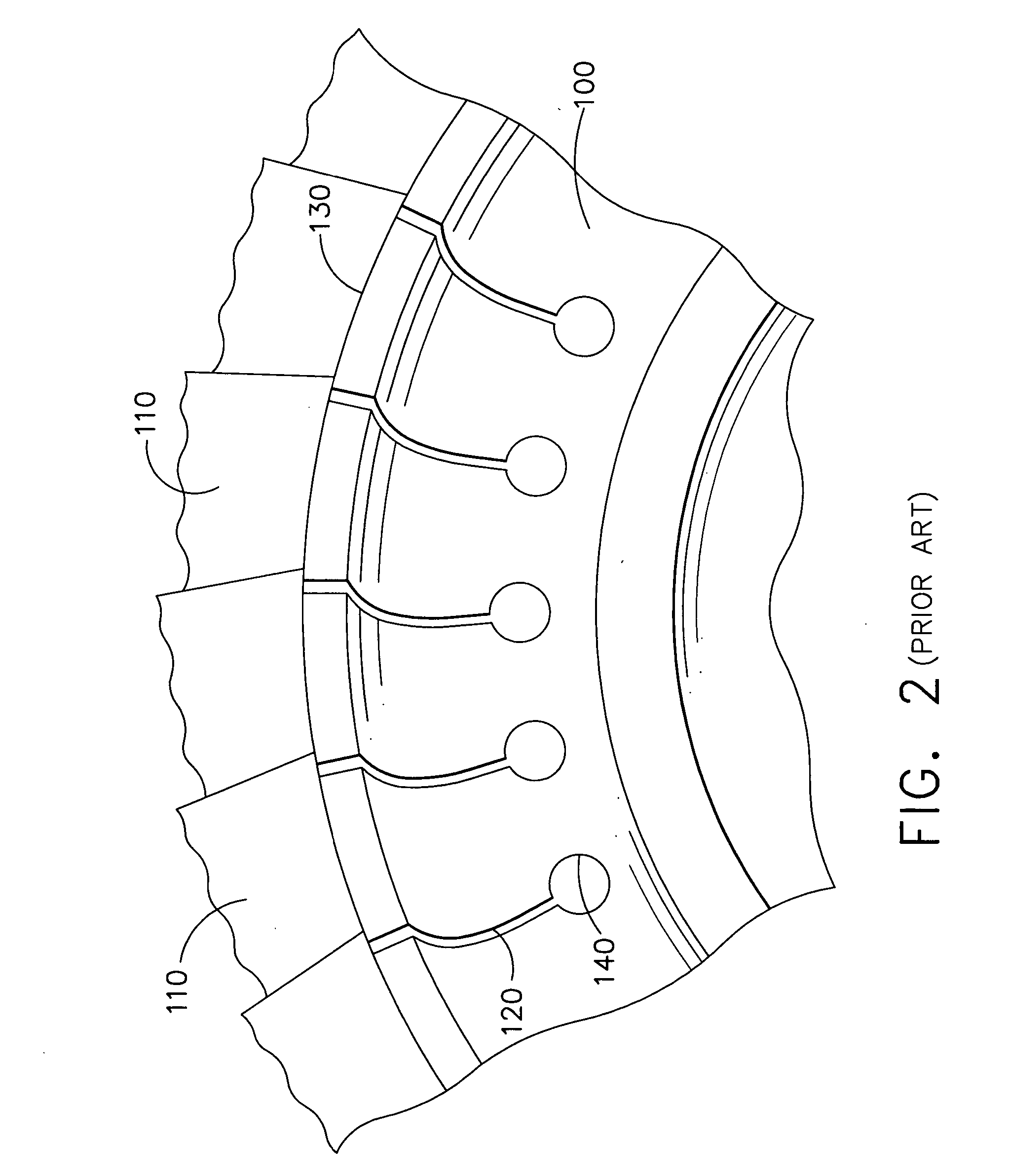
a technology of stress relief mechanism and gas turbine engine, which is applied in the direction of marine propulsion, vessel construction, lighting and heating apparatus, etc., can solve the problems of frequent vibration dislodging of rivets inserted into the drilled hole, laborious, time-consuming, and laborious sequence,

Active Publication Date: 2006-05-11
HONEYWELL INT INC
View PDF10 Cites 27 Cited by
  • Summary
  • Abstract
  • Description
  • Claims
  • Application Information

AI Technical Summary

Benefits of technology

[0018] In still another aspect of the invention, an electric discharge wi

Problems solved by technology

Such turbine disks have been observed to develop fractures along the circumference of the disk during use.
However, there are a number of problems associated with this mechanism: First, the method of fabricating the hoop stress relief mechanism involves a detailed sequence of operations that must be precisely executed.
This sequence is labor intensive, time consuming, and exacting, and thus expensive.
Second, the rivet inserted into the drilled hole is frequently dislodged by vibration, thermal shock, or mechanical means during use.
The rivet thus released can cause downstream damage within the turbine.
Also, hot gases may subsequently leak through the turbine disk and reduce engine efficiency.
A third problem is that rivets have varying tolerances, so that when installed, they present a balancing problem.
As the turbine rotates more rapidly, rivets that are mismatched as to size, weight, or placement along the circumference of the disk start producing unacceptable vibration.
Too much vibration can cause the entire turbine to fail.
A fourth problem is that there are variatio

Method used


Image

  • Hoop stress relief mechanism for gas turbine engines
  • Hoop stress relief mechanism for gas turbine engines
  • Hoop stress relief mechanism for gas turbine engines

Examples


Embodiment Construction

[0030] The following detailed description is of the best currently contemplated modes of carrying out the invention. The description is not to be taken in a limiting sense, but is made merely for the purpose of illustrating the general principles of the invention, since the scope of the invention is best defined by the appended claims.

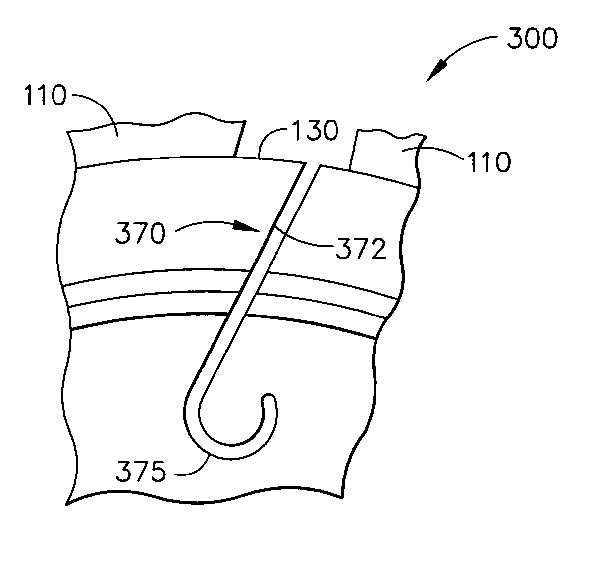
[0031] The invention provides an innovative mechanism for relieving fractures along the rim of a rotating body that may be caused by hoop stress forces. The innovative mechanism may be a slot extending inwardly from the rim in a generally radial direction and terminating in a curved portion. The slot may extend through the disk of the rotating body. Fabricating such a stress relieving slot in the circumferential rim of a disk may be inexpensive since it does not involve as many steps as the rivet mechanism described previously. There is minimal leakage through the disk and the slot may be essentially free from any hole drilling surface anomalies that ...


PUM

PropertyMeasurementUnit
Angleaaaaaaaaaa
Angleaaaaaaaaaa
Angleaaaaaaaaaa

Abstract

A hoop stress relief mechanism is disclosed for use on a rotary body to relieve stress caused by both thermal and centrifugal forces. The mechanism may consist of a J-shaped slot cut from the outer rim of the rotary body a distance inwardly toward the axis of rotation, the slot having a curve in its inward end that curves back towards the outer rim. The J-shaped slot may extend through the rotary body to join its two faces. The J-shaped slot may be fabricated by an electric discharge wire machine. The electric discharge wire machine may make multiple passes in order to smooth the bottom surface of the curved slot portion.

Description

BACKGROUND OF THE INVENTION [0001] The present invention generally relates to articles of manufacture and methods of fabrication for mechanisms to relieve hoop stress in rotating bodies and, more specifically, to a J-slot modification to a rotating disk having integral cast blades such as those contained in a gas turbine engine. [0002] Hoop stress is defined as a load measured in the direction of the circumference of a rotating body, the load being created by thermal gradients and centrifugal forces acting in a radial direction outwardly from the axis of rotation of the body. Such stress is particularly acute in the art of gas turbine engine design where the turbine disks may have integrally cast blades. Such turbine disks have been observed to develop fractures along the circumference of the disk during use. [0003] A number of methods were devised to prevent such fractures. Initially a series of circumferential slots were fabricated into the outer edge of the disk and extending inw...

Claims


Application Information

Patent Timeline
IPC IPC(8): B64C11/16
CPCB23H9/10F01D5/34F05D2260/941F05D2250/70F05D2230/12
Inventor RICE, DEREK A.WALDMAN, DAVID R.HOW, REDGESERAG, MAHER A.RIPPEY, PAUL D.SILCOX, CHARLES P.HENRY, CHESTER L.LIU, HSIN-YIHRUSKA, PAUL E.JACKSON, RICHARD E.INNES, DAVID A.BAILEY, GORDON B.
Owner HONEYWELL INT INC
Why Eureka
Try Eureka