Method and apparatus for controlling hydraulic pump for working machine of working vehicle

a technology for working machines and hydraulic pumps, which is applied in the direction of fluid couplings, servomotors, instruments, etc., can solve the problems of large power loss, slow speed of working machines, and inability to always perform excavating operations, so as to reduce power loss, efficient operation, and efficient operation

Inactive Publication Date: 2006-05-11
KOMATSU LTD
View PDF10 Cites 16 Cited by
  • Summary
  • Abstract
  • Description
  • Claims
  • Application Information

AI Technical Summary

Benefits of technology

[0020] According to the above constitution, when the predetermined time elapses with the hydraulic pressure in the bottom side of the cylinder at the predetermined value or less, and thereafter, the hydraulic pressure exceeds the predetermined value, the displacement of the hydraulic pump is reduced to the predetermined displacement. Namely, since it is reliably detected that the working vehicle is under excavating operation, and the pump displa

Problems solved by technology

If a fixed displacement type hydraulic pump is used in such a case, a large amount of pressure oil is returned into a tank, and large power loss is caused.
However, in the above described method, the following problems exist.
However, in this case, excavating operation is not always performed, but the working vehicle is approaching a predetermined place while operating the working machine with the forward and first speed gear in some cases.
In such a case, the speed of the working machine becomes slow, and the working efficiency sometimes reduces.
Depending on the soil property, an operation is sometimes performed with

Method used


Image

  • Method and apparatus for controlling hydraulic pump for working machine of working vehicle
  • Method and apparatus for controlling hydraulic pump for working machine of working vehicle
  • Method and apparatus for controlling hydraulic pump for working machine of working vehicle

Examples


first embodiment

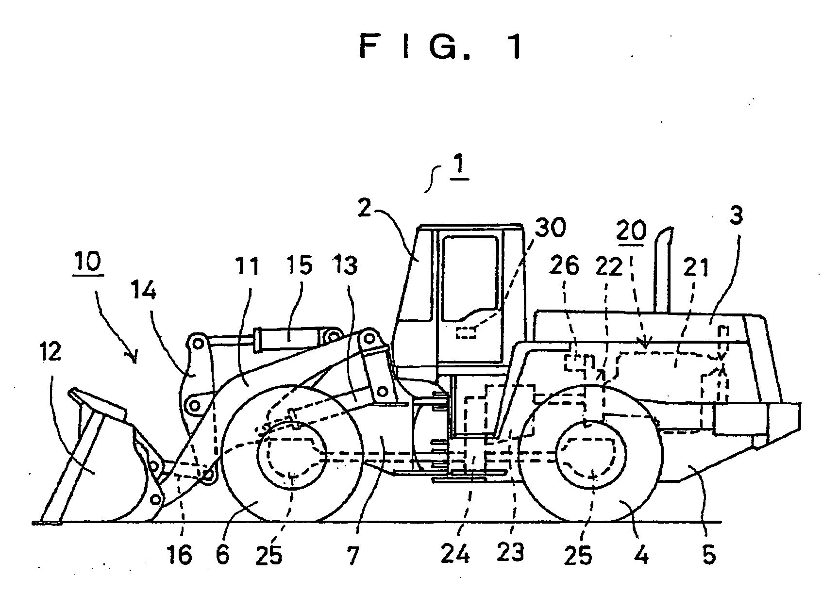
[0035] A first embodiment will be explained below. FIG. 1 is a side view of a wheel loader which is one example of the working vehicle. In FIG. 1, a working vehicle 1 has a rear vehicle body 5 having a driver's cab 2, an engine frame 3 and rear wheels 4 and 4, and a front frame 7 having front wheels 6 and 6. A working machine 10 is mounted to the front frame 7. Namely, a bucket 12 is swingably mounted to a tip end portion of a lift arm 11 of which base end portion is swingably mounted to the front frame 7. The front frame 7 and the lift arm 11 are connected by a set of lift cylinders 13 and 13, and the lift arm 11 swings by extending and contracting the lift cylinders 13 and 13.

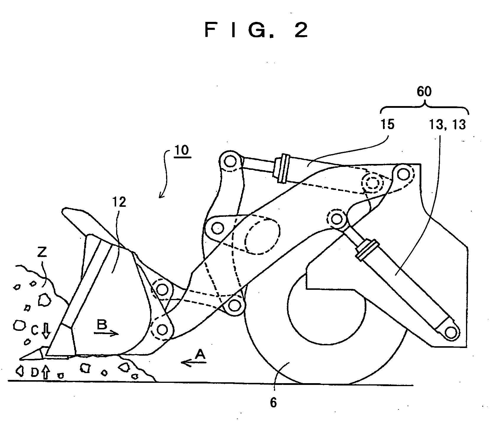
[0036] A substantially central portion of the tilt art 14 is swingably supported at the lift arm 11, and one end portion of the tilt arm 14 and the front frame 7 are connected by a tilt cylinder 15. The other end portion of the tilt arm 14 and the bucket 12 are connected by a tilt rod 16, and when the tilt cy...

second embodiment

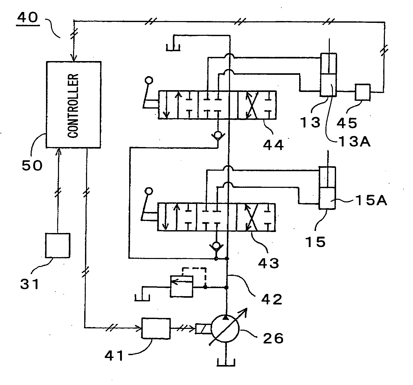
[0054] Next, the method and apparatus for controlling a hydraulic pump for a working machine of a working vehicle according to the present invention will be described in detail with reference to FIGS. 6 to 8. FIG. 6 differs from FIG. 1 in the respect that a bucket height detector 32 is included in the wheel loader 1. FIG. 7 is a system diagram showing one example of a control apparatus 40A. The control apparatus 40A differs from the control apparatus 40 in FIG. 4 in the respect that the control apparatus 40A includes the bucket height detector 32. FIG. 8 differs from FIG. 5 in the respect that step 118 is added. Accordingly, in the explanation in FIGS. 6 to 8, the same reference numerals and characters are given to the same portions as explained in FIGS. 1 to 5, and the explanation of them will be omitted.

[0055] As shown in FIG. 6, the front frame 7 includes the bucket height detector 32 for detecting the position of the top surface of the base end portion of the lift arm 11 with re...


PUM


Abstract

A hydraulic pump displacement control apparatus for a working vehicle capable of reliably detecting the working vehicle under excavating operation and reducing loss in power is provided. For this purpose, the control apparatus includes a bottom pressure detector (45) for detecting a hydraulic pressure in a bottom side (13A) of a cylinder (60) for operating a working machine (10), a displacement control device (41) for controlling a displacement of a variable displacement hydraulic pump (26), and a controller (50) which determines that an excavating operation starts when a predetermined time elapses with a detection value from the bottom pressure detector at a predetermined value or less and thereafter, the detection value exceeds the predetermined value, and outputs a displacement control signal to reduce the displacement of the hydraulic pump to a predetermined displacement that is smaller than the maximum displacement to the displacement control device.

Description

TECHNICAL FIELD [0001] The present invention relates to a method and apparatus for controlling a displacement of a hydraulic pump for a working machine of a working vehicle, particularly, a vehicle for construction work. BACKGROUND ART [0002] For example, in a hydraulic system for driving a working machine of a wheel loader which is a vehicle for construction work, there is the case where a hydraulic pressure is required, but only a small discharge amount is required at the time of an excavating operation or the like. If a fixed displacement type hydraulic pump is used in such a case, a large amount of pressure oil is returned into a tank, and large power loss is caused. In order to reduce the power loss, there is provided a method of reducing a pump discharge amount at the time of an excavating operation by using a variable displacement type hydraulic pump. As one example of this, there is the one disclosed in the U.S. Pat. No. 6,073,442. According to this, the method is for contro...

Claims


Application Information

Patent Timeline
IPC IPC(8): F04B49/00E02F9/22F15B11/00F15B11/16F15B21/08
CPCE02F9/2235E02F9/2296F15B11/165F15B21/087F15B2211/20553F15B2211/255F15B2211/30505F15B2211/30525F15B2211/3111F15B2211/31576F15B2211/324F15B2211/327F15B2211/55F15B2211/605F15B2211/63F15B2211/6652F15B2211/7051F15B2211/7107F15B2211/76F15B2211/765F15B2211/88
Inventor TODA, EIJISATO, YOSHIHARU
Owner KOMATSU LTD
Why Eureka
Try Eureka