Method and device for transmission with reduced crosstalk

a transmission method and crosstalk technology, applied in the field of methods and devices for transmission with reduced crosstalk, can solve the problems of not being able to describe all interconnections, not having specific physical characteristics, and being economically disadvantageous

Inactive Publication Date: 2006-05-11
RAMBUS INC +1
View PDF8 Cites 14 Cited by
  • Summary
  • Abstract
  • Description
  • Claims
  • Application Information

AI Technical Summary

Problems solved by technology

However, a priori no specific physical characteristic distinguishes what we have called a transmission conductor (which some authors call a signal conductor) from the reference conductor.
Besides, this model is not capable of describing all interconnections.
The techniques of 1) and 2) above, which are often implemented on twisted pair cables, achieve excellent performance, but they require the use of two transmission conductors for each signal to be sent, which is economically disadvantageous.
They are difficult to implement beyond a few hundred megahertz.
The technique of 7

Method used


Image

  • Method and device for transmission with reduced crosstalk
  • Method and device for transmission with reduced crosstalk
  • Method and device for transmission with reduced crosstalk

Examples


first embodiment

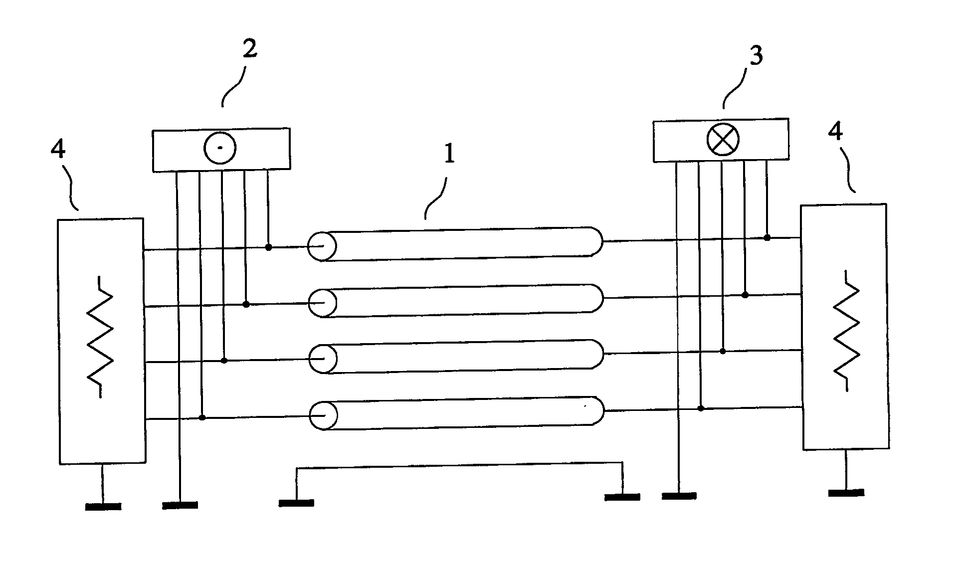
[0128] As a first example of a device for implementing the method of the invention, given by way of non-limiting example, we have represented in FIG. 3 a device of the invention comprising an interconnection (1) having four parallel transmission conductors and a reference conductor. The transmission conductors numbered 1, 2, 3 and 4 (this numbering is not shown in FIG. 3) may be the conductors of a flat cable fitted with a screen (or shielding), this screen being used as reference conductor. In FIG. 3, the two ends of the interconnection are each connected to a termination circuit (4) presenting an impedance matrix approximating the characteristic impedance matrix in a known frequency band. The transmitting circuit (5) receives at its input the signals of the four channels of the source (2), and its four output terminals are connected to the conductors of the interconnection, this transmitting circuit producing modal voltages on these conductors, each modal voltage being proportiona...

second embodiment (

Best Mode)

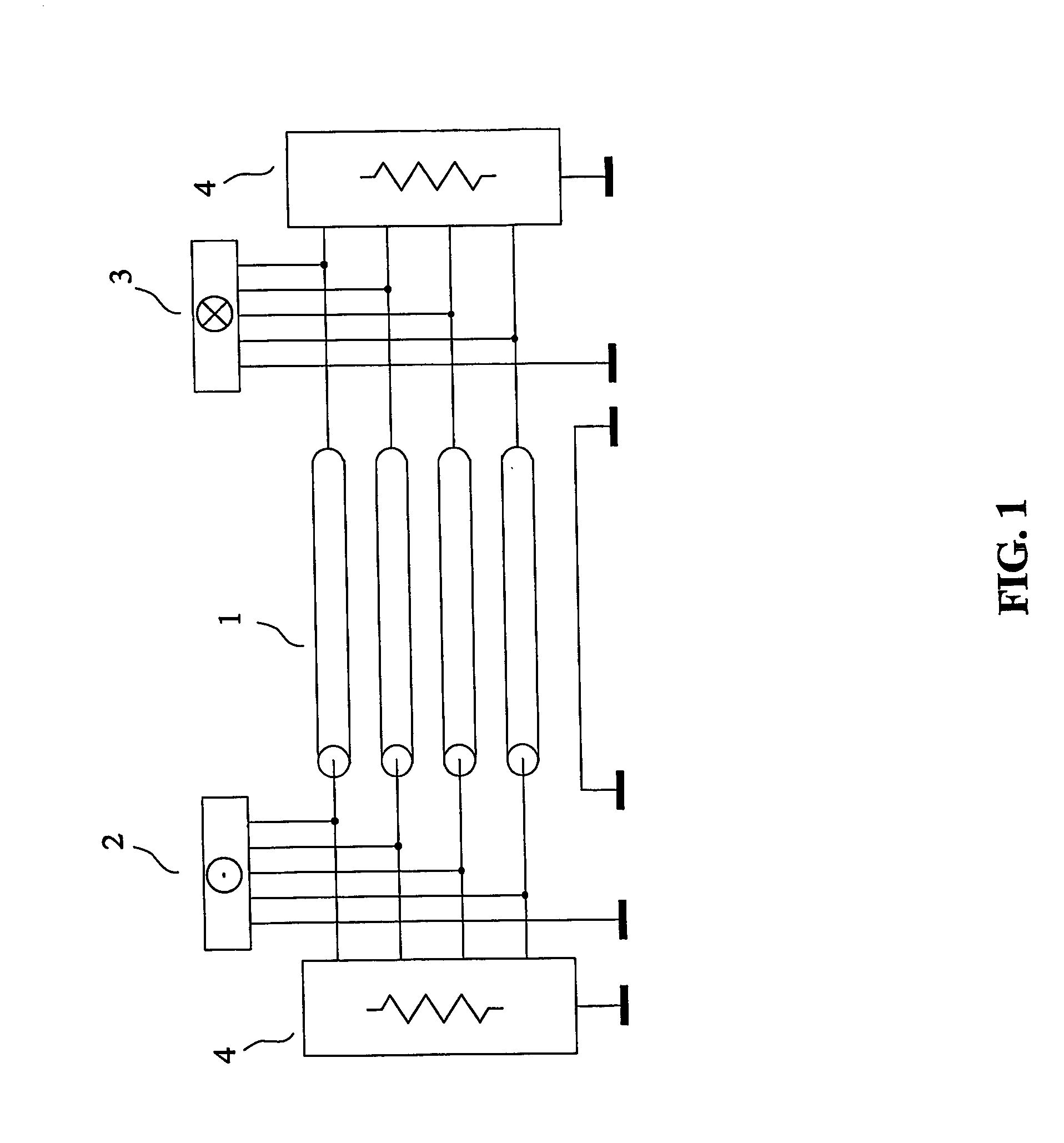
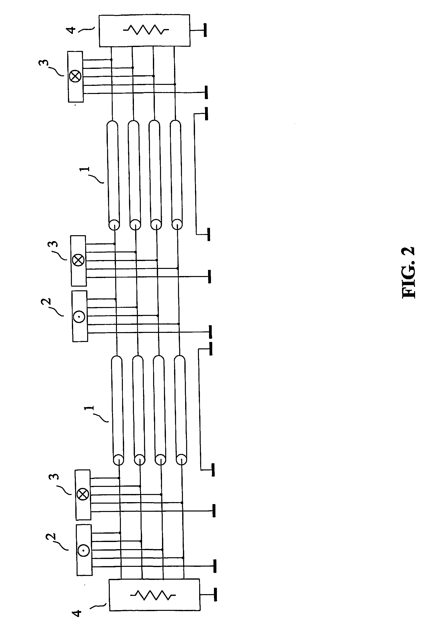
[0131] As a second example of a device for implementing the method of the invention, given by way of non-limiting example and best mode of carrying out the invention, we have represented in FIG. 4 a device of the invention, comprising an interconnection (1) having four parallel transmission conductors, and a reference conductor. The interconnection is connected at each end to a termination circuit (4). Two transmitting circuits (5) placed at two different abscissa z, receive at their inputs the signals from the four channels of each of the two sources (2), these transmitting circuits (5) producing, when they are active, modal voltages, each being proportional to the signal of one channel. Note that this is a data bus architecture, and that the signals needed to obtain the active state of at most one transmitting circuit at a given time are not shown in FIG. 4. The three receiving circuits (6) placed at three different abscissa z, have their input terminals connected to the...

third embodiment

[0133] As a third example of a device for implementing the method of the invention, given by way of non-limiting example, we have considered the application of the method of the invention inside an integrated circuit in gallium arsenide technology, confining ourselves to discussing the creation of the termination circuit(s). A paper by J. Chilo entitled “Modélisation et analyse temporelle d'un bus d'interconnexion en technologie GaAs”, published in Annales des télécommunications, vol. 40, No. 3-4, Mars-Avril l985, provides the L and C matrices of such an interconnection with 8 transmission conductors: L=(0,570,210,110,060,040,030,020,010,210,570,210,110,060,040,030,020,110,210,560,210,110,060,040,030,060,110,210,560,210,110,060,040,040,060,110,210,560,210,110,060,030,040,060,110,210,560,210,110,020,030,040,060,110,210,570,210,010,020,030,040,060,110,210,57)⁢μ⁢ ⁢H⁢ / ⁢mC=(465-156-16-5-3-2-1-1-156523-150-14-4-2-1-1-16-150523-150-14-4-2-2-5-14-150523-150-14-4-3-3-4-14-150523-150-14-5-2-...


PUM


Abstract

The invention relates to a method and a device for transmission with reduced crosstalk in interconnections used for sending a plurality of signals, such as the interconnections made with flat multiconductor cables, or with the tracks of a printed circuit board, or inside an integrated circuit. An interconnection with four parallel transmission conductors plus a reference conductor has each of its ends connected to a termination circuit. The transmitting circuit receives at its input the signals of the four channels of the source and its output terminals are connected to the conductors of the interconnection. The receiving circuit's input terminals are connected to the conductors of the interconnection, and its four output channels are connected to the destination. The signals of the four channels of the source are sent to the four channels of the destination, without noticeable crosstalk.

Description

FIELD OF THE INVENTION [0001] The invention relates to a method and a device for transmission with reduced crosstalk through interconnections used for sending a plurality of signals, such as the ones made with flat multiconductor cables, or with the tracks of a printed circuit board, or inside an integrated circuit. [0002] The French patent application number 0300064 of 6 Jan. 2003, entitled “Procédé et dispositif pour la transmission avec une faible diaphonie” is incorporated by reference. PRIOR ART [0003] Let us first consider the theoretical problem of an interconnection with n transmission conductors placed close to a reference conductor. Let us number these conductors from 0 to n, where 0 is the “reference conductor” which will be used as a reference for measuring voltages, and which is often called the ground conductor. [0004] As an example, we have represented in FIG. 1 an interconnection with four parallel transmission conductors (1) between a source (2) and a destination (3...

Claims


Application Information

Patent Timeline
IPC IPC(8): H04B1/10H04B15/00H04B7/005H04B3/32H04B3/46H04L5/20H04L25/02H04L25/08
CPCH04B3/32H04L5/20H04L25/0272H04L25/0278H04B3/487H04L25/0292H04L25/08Y10S439/941H04L25/028
Inventor BROYDE, FREDERICCLAVELIER, EVELYNE
Owner RAMBUS INC
Why Eureka
Try Eureka