
Method and device for liposuction

a liposuction and liposuction technology, applied in the field of liposuction, can solve the problems of limiting the use of liposuction in delicate areas, affecting and affecting the accuracy of liposuction, so as to facilitate microliposuction in the area, improve the precision of liposuction

Inactive Publication Date: 2006-05-11
DOBAK JOHN D III
View PDF11 Cites 33 Cited by
  • Summary
  • Abstract
  • Description
  • Claims
  • Application Information

AI Technical Summary

Benefits of technology

[0007] Advantages of certain systems may include one or more of the following. Certain systems may safely improve the precision of liposuction. Certain systems may facilitate microliposuction in areas of the face such as the periorbital region with probes less than 2.0 mm in diameter. Certain systems may help preserve blood vessels and nerves. Certain systems may safely allow intraperitoneal liposuction.

Problems solved by technology

All of these techniques suffer similar problems, which include excessive blood loss, skin dimpling and irregularities, perforation, and skin burns.
In addition, current techniques can damage blood vessels and nerves.
These problems limit the use of liposuction in delicate areas such as the periorbital fat region, where sagging and bulging tissue can form.
Traditional liposuction probes, which may be, e.g., 4-8 mm in diameter, are too large and the mechanical forces required to disrupt the fat tissue can damage surrounding structures.
For similar reasons, liposuction of the face in general is even more precarious using traditional instrumentation.
The above-mentioned problems with current liposuction systems also prevent liposuction from being performed in the peritoneal cavity.

Method used


Image

  • Method and device for liposuction
  • Method and device for liposuction
  • Method and device for liposuction

Examples


Embodiment Construction

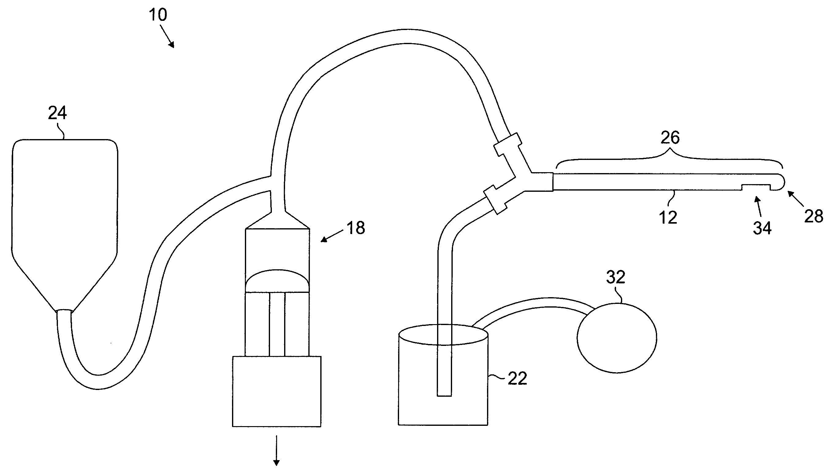
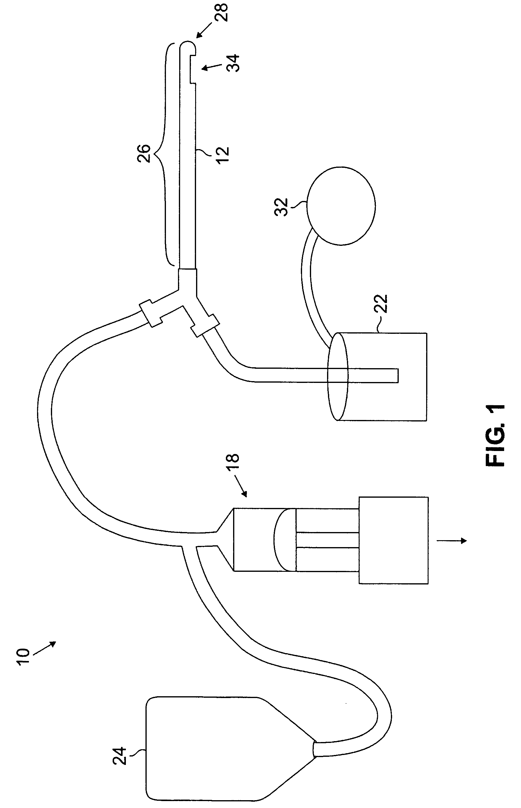
[0012] Referring to FIGS. 1 and 2, an integrated system 10 includes a cannula 12 with a high pressure inlet lumen 14 and a lower pressure outlet lumen 16, a high pressure pump or source of compressed gas 18, an evacuation container or reservoir 22, and a source of liquid such as a fat emulsifying solution 24. An optional vacuum pump 32 may also be employed.

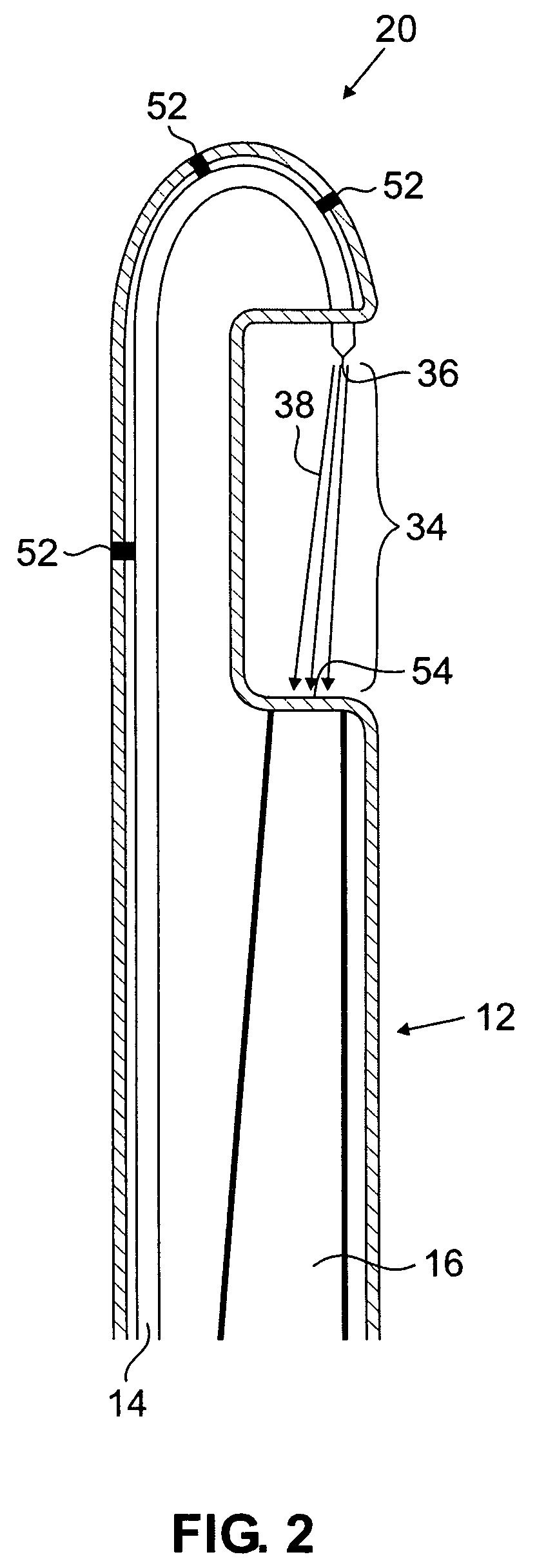
[0013] The cannula 12 typically has a body 26 of variable length depending on the procedure and a blunt tip 28. The cannula diameter may range from 1.5-8.0 mm and may be shaped to facilitate liposuction in a given area. For example, facial liposuction may be conducted with a cylindrical probe 20 as shown in FIG. 2. Referring to FIG. 3, intraperitoneal liposuction may be conducted with a curved cylindrical probe or a probe 30 that flattens out in the horizontal plane similar to a vacuum cleaner. An exhaust outlet 36 is structured and configured to create a jet spray 38, as explained in greater detail below. Just proximal to the ro...


PUM


Abstract

Systems and methods for liposuction are disclosed that use a lipid-emulsifying fluid to produce fluid jet disruption and Venturi pumping of fat tissue. The device includes a flexible or rigid probe with an inlet lumen and an outlet lumen. The inlet lumen is in fluid communication with a pump capable of producing high pressures, e.g., 250-3500 psi. The pump is in fluid communication with a volume of a liquid such as sterile saline that may or may not contain a fat emulsifier. At the end of the inlet lumen is a conical constriction or a port that accelerates the emulsification fluid to high velocities. The high velocity jet stream creates a low pressure area that draws the fat tissue into proximity with the jet stream. The jet stream directly and through turbulent vortices breaks up the fat cells. The lipid of the fat cells is subsequently emulsified by the emulsification fluid.

Description

CROSS-REFERENCE TO RELATED APPLICATIONS [0001] This application claims the benefit of priority of U.S. Provisional Patent Application Ser. No. 60 / 626,579, filed Nov. 10, 2004, entitled “Method and Device for Liposuction”.BACKGROUND [0002] Liposuction is performed to remove subcutaneous fat from the body as a cosmetic procedure to improve appearance. Traditional liposuction is performed using a suction cannula that is moved in a continuous fashion in the subcutaneous tissue to disrupt fat cells and evacuate the debris. Cells are disrupted mechanically. In tumescent techniques, saline mixed with a vasoconstricting drug such as epinephrine is injected into the fat tissue prior to suction. Other techniques to facilitate liposuction include ultrasonic disruption of cells, probe vibration, moving scalpel blades, and laser illumination. All of these techniques suffer similar problems, which include excessive blood loss, skin dimpling and irregularities, perforation, and skin burns. In addi...

Claims


Application Information

Patent Timeline
IPC IPC(8): A61M1/00
CPCA61B17/3203A61M1/0058A61M1/0084A61M2202/08A61M1/85A61M1/89A61M1/892A61M1/804
Inventor DOBAK, JOHN D. III
Owner DOBAK JOHN D III
Learn More