Start controller for internal combustion engine

a technology for starting controllers and internal combustion engines, which is applied in the direction of engine starters, electric control, machines/engines, etc., can solve the problems of difficult to precisely control the engine speed of the engine, and the system is hardly applied to a vehicle, so as to enhance the startability

Active Publication Date: 2006-05-18
DENSO CORP
View PDF8 Cites 19 Cited by
  • Summary
  • Abstract
  • Description
  • Claims
  • Application Information

AI Technical Summary

Benefits of technology

[0010] The present invention is made in view of the foregoing matter and it is an object of the present invention to provide a start controller capable of precisely controlling the engine speed at starting to enhance the startability.

Problems solved by technology

Thus, it is hard to precisely control the engine speed of the engine by controlling the intake air flow rate.
However, such a system is hardly applied to a vehicle which is driven by only the internal combustion engine.

Method used


Image

  • Start controller for internal combustion engine
  • Start controller for internal combustion engine
  • Start controller for internal combustion engine

Examples


first embodiment

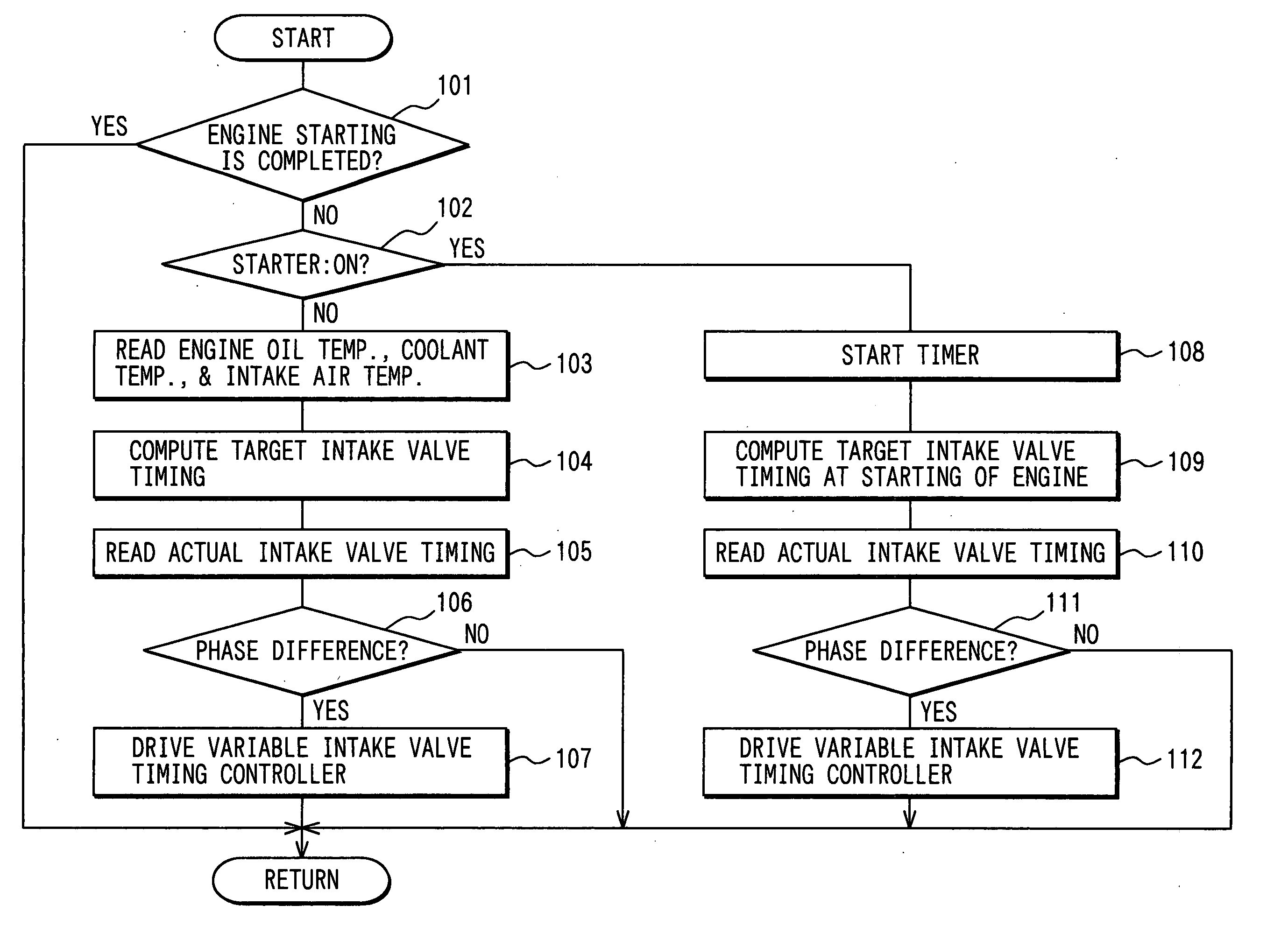
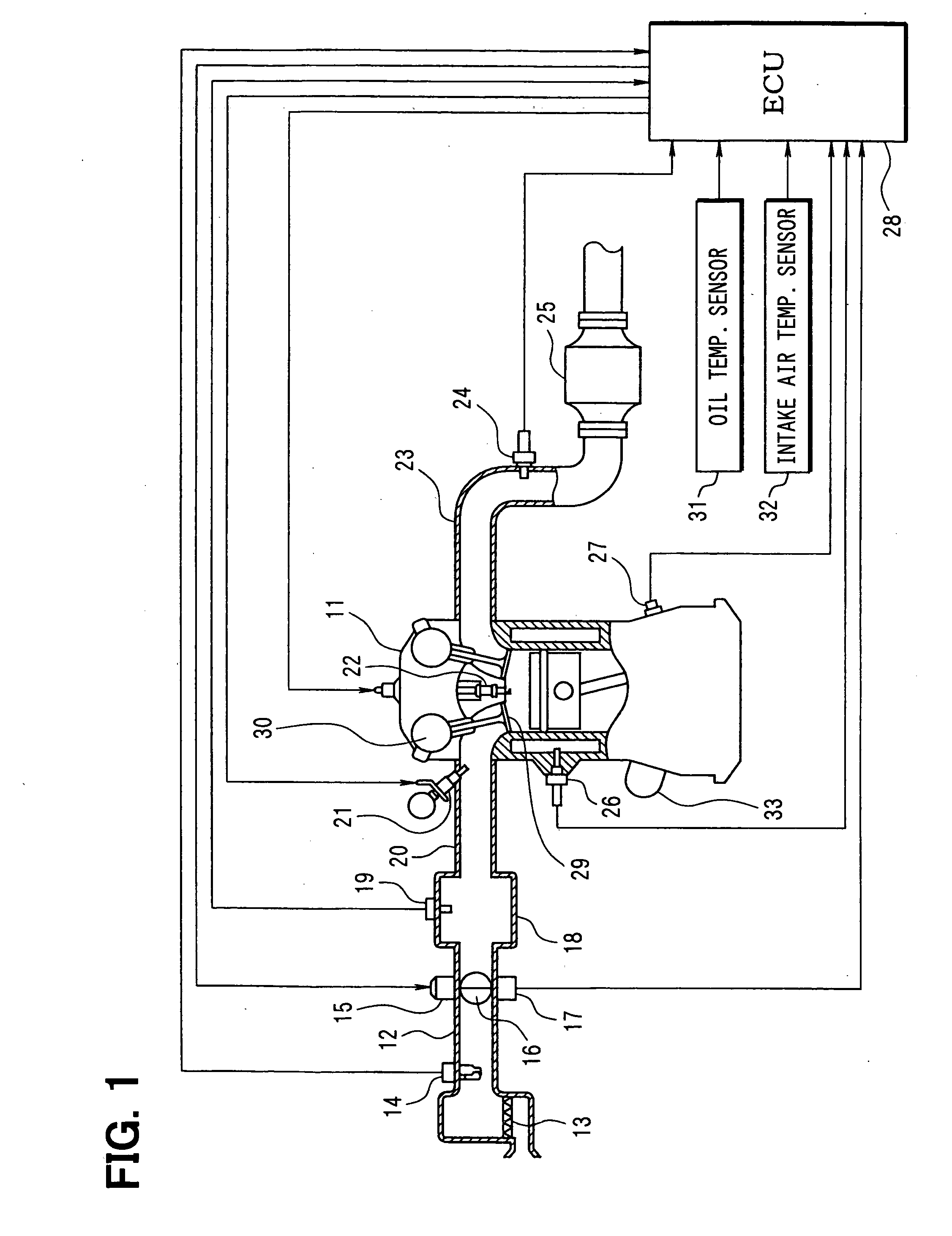
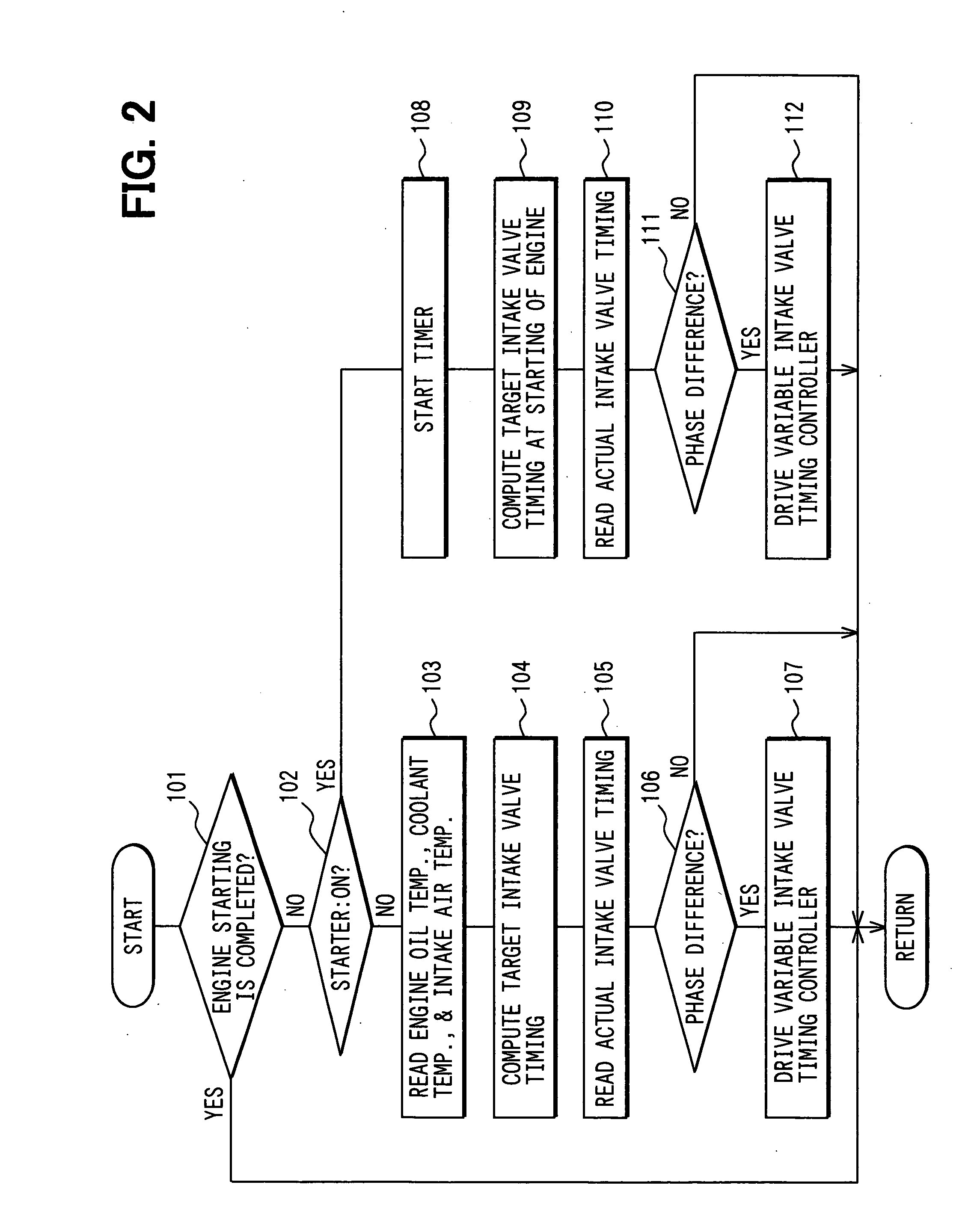
[0024] Referring to FIGS. 1 to 4, a first embodiment is described. FIG. 1 is a schematic view of an engine control system. An air cleaner 13 is arranged upstream of an intake pipe 12 of an internal combustion engine 11. An airflow meter 14 detecting an intake air flow rate is provided downstream of the air cleaner 13. A throttle valve 16 driven by a DC-motor 15 and a throttle position sensor 17 detecting a throttle position are provided downstream of the air flow meter 14.

[0025] A surge tank 18 including an intake air pressure sensor 19 is provided down stream of the throttle valve 16. The intake air pressure sensor 19 detects intake air pressure. An intake manifold 20 is connected to the surge tank 18. A fuel injector 21 is mounted on the intake manifold 20 at a vicinity of an intake air port. A spark plug 22 is mounted on a cylinder head of the engine 11 corresponding to each cylinder to ignite air-fuel mixture in each cylinder. The spark plug generate spark to ignite a fuel-air ...

second embodiment

[0050] Referring to FIGS. 5 and 6, a second embodiment is described hereinafter.

[0051] Due to a specification of a driving motor in the variable valve timing controller or a control position of the variable intake valve timing controller 30 at the time when the engine is stopped, there is a possibility that the actual valve timing cannot become the target intake valve timing corresponding to the target intake air flow rate of the initial combustion cylinder at the time of starting engine.

[0052] In the second embodiment, the ECU 28 controls the variable intake valve timing controller 30 in such a manner that the actual intake valve timing is consistent with the target intake valve timing by executing a program shown in FIG. 5 at the time when the engine is stopped, in which the target intake valve timing for next engine starting is established. Furthermore, by executing a program shown in FIG. 6, while the engine 11 is off, the target intake valve timing for the next engine startin...

third embodiment

[0062] As shown in FIG. 9, the starter 33 starts cranking of the engine 11 in a situation that the variable intake valve timing controller 30 retards the actual intake valve timing so that the actual compression ratio is decreased to a level in which the vehicle vibration is reduced at cranking. At the time when the engine speed is increased by cranking so that the vehicle vibration is reduced to a predetermined level, the ignition is started. The actual intake valve timing is gradually advanced during cranking in such a manner as to gradually increase the actual compression ratio according to cranking duration (or engine speed). Thereby, the actual compression ratio is increased to a ratio in which the engine 11 is driven by the combustion pressure at the same time as the combustion start timing.

[0063] The processes of the start control program shown in FIGS. 7 and 8 are described hereinafter.

[0064] In step 1101, at least one of coolant temperature, engine oil temperature, intake...


PUM


Abstract

At an intake timing of an initial combustion cylinder, an actual intake valve timing is adjusted to a target intake valve timing corresponding to a target intake air flow rate of the initial combustion cylinder. At intake timing of the other cylinders which contributes to increment of the engine speed after the initial combustion, the actual intake valve timing is adjusted to a target valve timing corresponding to a target intake air flow rate of the other cylinders. Thereby, the intake air flow rate of each cylinder is accurately controlled, so that the increment of the engine speed is restricted within a range in which a startability is not deteriorated and a vehicle vibration and an over shoot of the engine speed is appropriately restricted.

Description

CROSS REFERENCE TO RELATED APPLICATIONS [0001] This application is based on Japanese Patent Applications No. 2004-331115 filed on Nov. 15, 2004 and No. 2004-367193 filed on Dec. 20, 2004, the disclosure of which are incorporated herein by reference. FIELD OF THE INVENTION [0002] The present invention relates to a start controller for an internal combustion engine that is provided with a variable valve controller. The variable valve controller varies opening / closing characteristics of an intake valve. BACKGROUND OF THE INVENTION [0003] The variable valve controller adjusts a valve timing or valve lift of an intake valve in order to improve output of the engine, to enhance fuel economy, and to reduce emission. [0004] JP-2002-213261A shows a start controller utilizing the variable valve controller in which the intake valve timing or intake valve lift is adjusted in such a manner that an intake air flow rate at starting of the engine becomes minimum quantity to ignite air-fuel mixture i...

Claims


Application Information

Patent Timeline
Patent Type & Authority Applications(United States)
IPC IPC(8): F02D41/06F02N99/00
CPCF02D13/0226F02D41/0002F02D41/062F02D2013/0292F02D2041/001F02N11/08Y02T10/42Y02T10/18Y02T10/12Y02T10/40
Inventor IZUMI, KAZUNARIURUSHIHATA, HARUYUKI
Owner DENSO CORP
Why Eureka
Try Eureka