Spark ignition device and internal combustion engine with the same
- Summary
- Abstract
- Description
- Claims
- Application Information
AI Technical Summary
Benefits of technology
Problems solved by technology
Method used
Image
Examples
embodiment 1
[0048] A first embodiment of the invention will be described below by using a gasoline engine as an example with reference to the drawings.
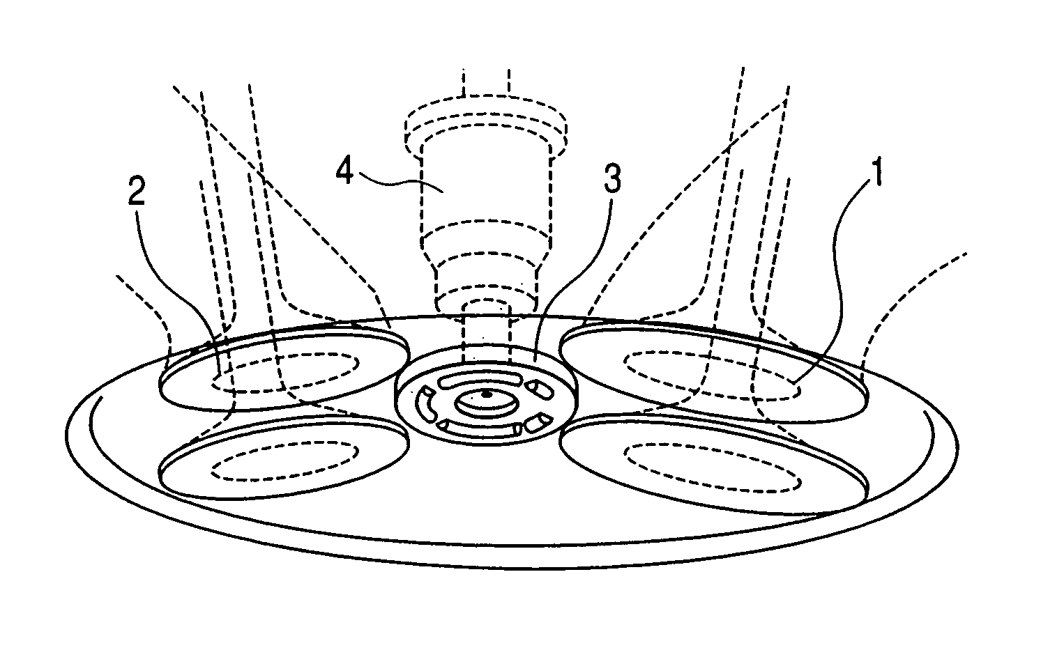
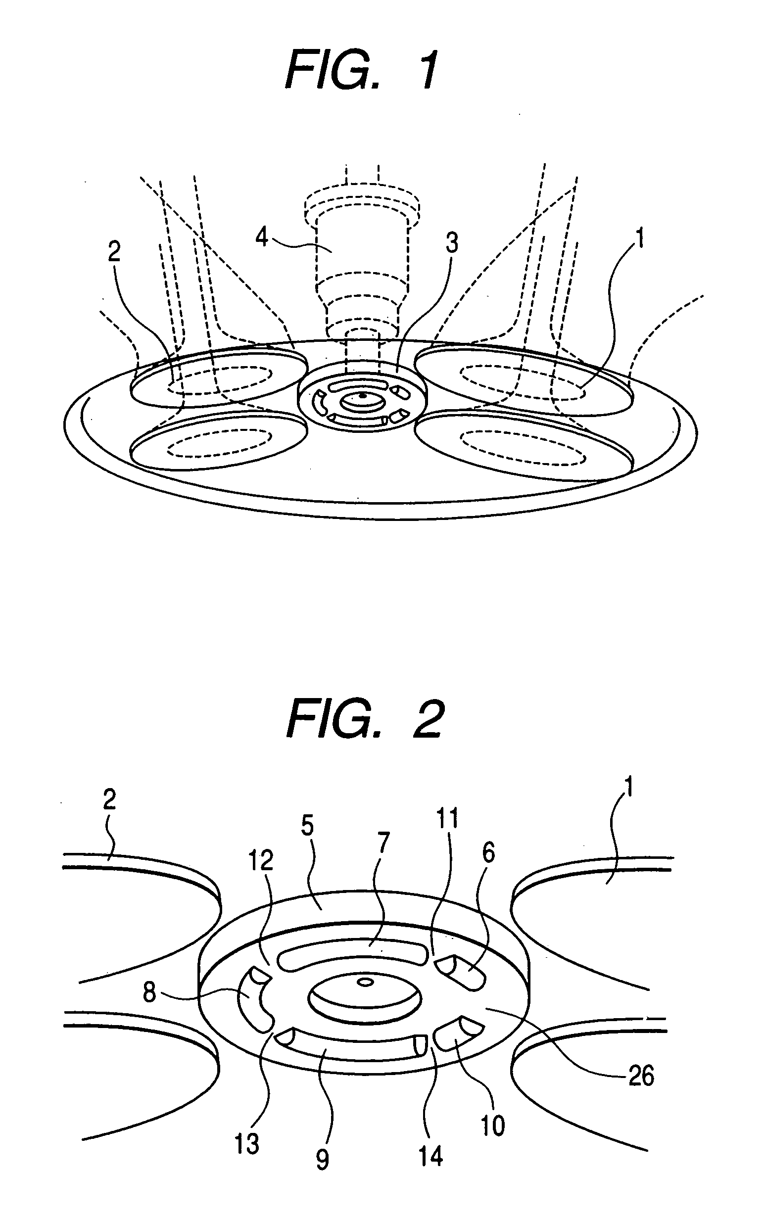
[0049]FIG. 1 is a perspective view showing, from a combustion chamber side, a state where a spark ignition device of the invention is attached to a cylinder head of an engine.
[0050] A spark ignition device in the embodiment includes an independent ignition type spark ignition device section (referring to a device in which an ignition coil unit obtained by integrating an ignition coil and an igniter is attached to the cylinder head of each cylinder), a spark plug section, and an injector section.
[0051] An electrode section 3 of the spark plug section of the spark ignition device is formed between an intake valve 1 and an exhaust valve 2 and, further, the nozzle of an injector (also called a fuel supply device or a fuel injection valve) 4 is disposed in the center of the electrode section 3.
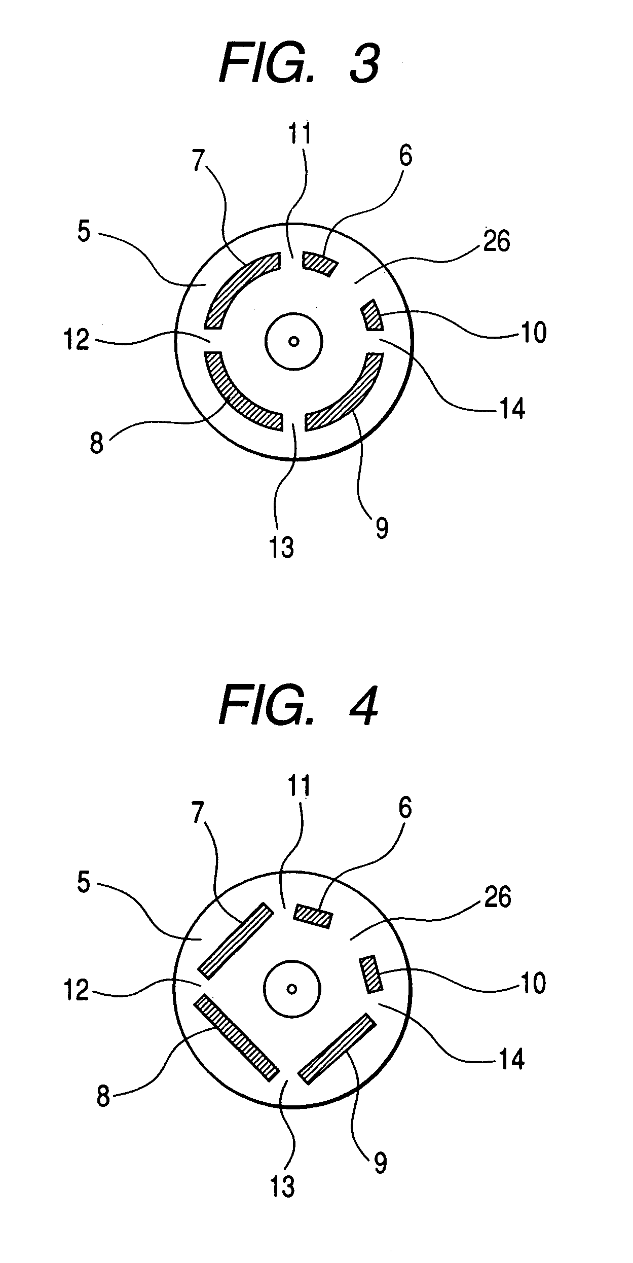
[0052] Next, the details of the electrode section 3 of...
second embodiment
[0062]FIGS. 5A and 5B show the structure of a so-called unit (which can be also called as a module) in which the injector 4, the spark electrode section 3 (spark plug section), and a spark ignition device (ignition coil section) 15 are integrated.
[0063]FIG. 5A is a cross section showing a portion where the spark electrode 6 for supplying spark voltage which will be described later is seen. FIG. 5B is an enlarged cross section of the portion where the spark electrode 10 to be connected to the earth is seen.
[0064] An insulating material layer 65 is formed around a nozzle 41 of the injector 4, and the injector 4 and the spark ignition device 15 are mechanically coupled to each other through the insulating material layer 65.
[0065] The spark ignition device 15 and the spark electrode 6 for supplying high voltage are connected through a conductor 61. The spark electrode 10 for the earth is connected to the body of the vehicle through a conductor 62. These conductors 61 and 62 are integ...
third embodiment
[0082] An embodiment of an in-cylinder direct injection / spark ignition type internal combustion engine using the spark ignition device with the fuel injection as an embodiment of the invention shown in FIG. 5 will be described with reference to FIGS. 7 to 12. FIG. 7 is a configuration diagram of the direct injection / spark ignition type engine.
[0083]FIG. 8 shows a section around the center of a combustion chamber of the direct injection / spark ignition type engine shown in FIG. 7.
[0084] The embodiment is a configuration example of the direct injection / spark ignition type engine for performing a uniform charge combustion drive mode and a stratified charge combustion drive mode. A cavity 50 is provided in a center of the crown (upper) face of a piston 21.
[0085] The cavity 50 has an almost hemisphere shape as shown in FIG. 8, and the diameter D of the opening of the cavity 50 is determined in the range of D=1L to 2L when the distance between the neighboring spark electrodes 6, . . . ,...
PUM
 Abstract
Description
Claims
Application Information
 - R&D
- Intellectual Property
- Life Sciences
- Materials
- Tech Scout
- Unparalleled Data Quality
- Higher Quality Content
- 60% Fewer Hallucinations
Browse by: Latest US Patents, China's latest patents, Technical Efficacy Thesaurus, Application Domain, Technology Topic, Popular Technical Reports.
© 2025 PatSnap. All rights reserved.Legal|Privacy policy|Modern Slavery Act Transparency Statement|Sitemap|About US| Contact US: help@patsnap.com


