Fuel supply apparatus

a technology of fuel supply and fuel injection, which is applied in the direction of fuel injection apparatus, charge feed system, electric control, etc., can solve the problems of failure of operation, failure of combustion, and decrease of power output,

Inactive Publication Date: 2006-05-18
TOYOTA JIDOSHA KK
View PDF3 Cites 53 Cited by
  • Summary
  • Abstract
  • Description
  • Claims
  • Application Information

AI Technical Summary

Benefits of technology

[0027] In the fuel supply apparatus, in the configuration where the first fuel supply system (low-pressure fuel supply system) and the second fuel supply system (high-pressure fuel supply system) are both provide and a plurality of first fuel delivery pipes are provide respectivel

Problems solved by technology

For example, if the quantity of the fuel injected from the intake manifold injector is smaller than a required injection quantity due to an insufficient discharge quantity of the low-pressure fuel pump, the air-fuel ratio (A/F) will become lean, thereby causing failure in combustion, decrease of power output, and degradation of exhaust emission property.
If the fuel supplied to the high-pressure fuel pump is insufficient, the fuel of an adequate quantity will not flow into a plunger portion constituting the high-pressure fuel pump, thereby causing operation failure due to poor lub

Method used


Image

  • Fuel supply apparatus
  • Fuel supply apparatus
  • Fuel supply apparatus

Examples


first embodiment

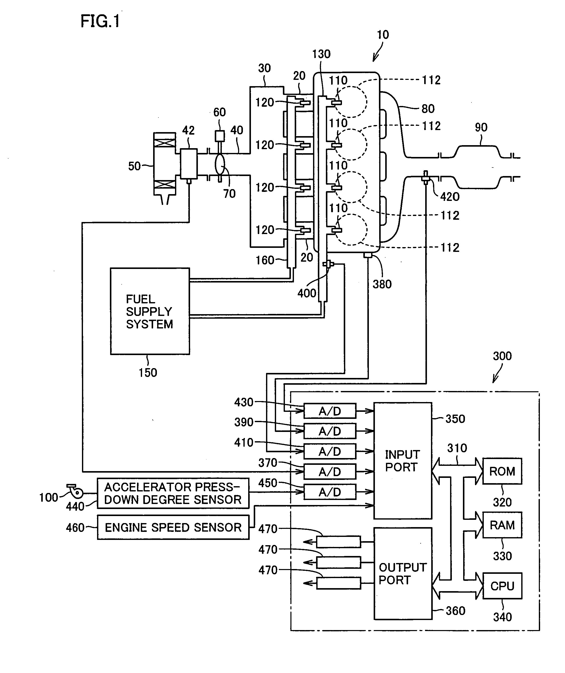
[0043]FIG. 1 schematically shows an engine system incorporating a fuel supply apparatus according to embodiments of the present invention. Although an in-line 4-cylinder gasoline engine is shown in FIG. 1, application of the present invention is not restricted to the engine shown.

[0044] As shown in FIG. 1, the engine (internal combustion engine) 10 includes four cylinders 112, which are connected via corresponding intake manifolds 20 to a common surge tank 30. Surge tank 30 is connected via an intake duct 40 to an air cleaner 50. In intake duct 40, an airflow meter 42 and a throttle valve 70, which is driven by an electric motor 60, are disposed. Throttle valve 70 has its degree of opening controlled based on an output signal of an engine ECU (Electronic Control Unit) 300, independently from an accelerator pedal 100. Cylinders 112 are connected to a common exhaust manifold 80, which is in turn connected to a three-way catalytic converter 90.

[0045] For each cylinder 112, an in-cyli...

second embodiment

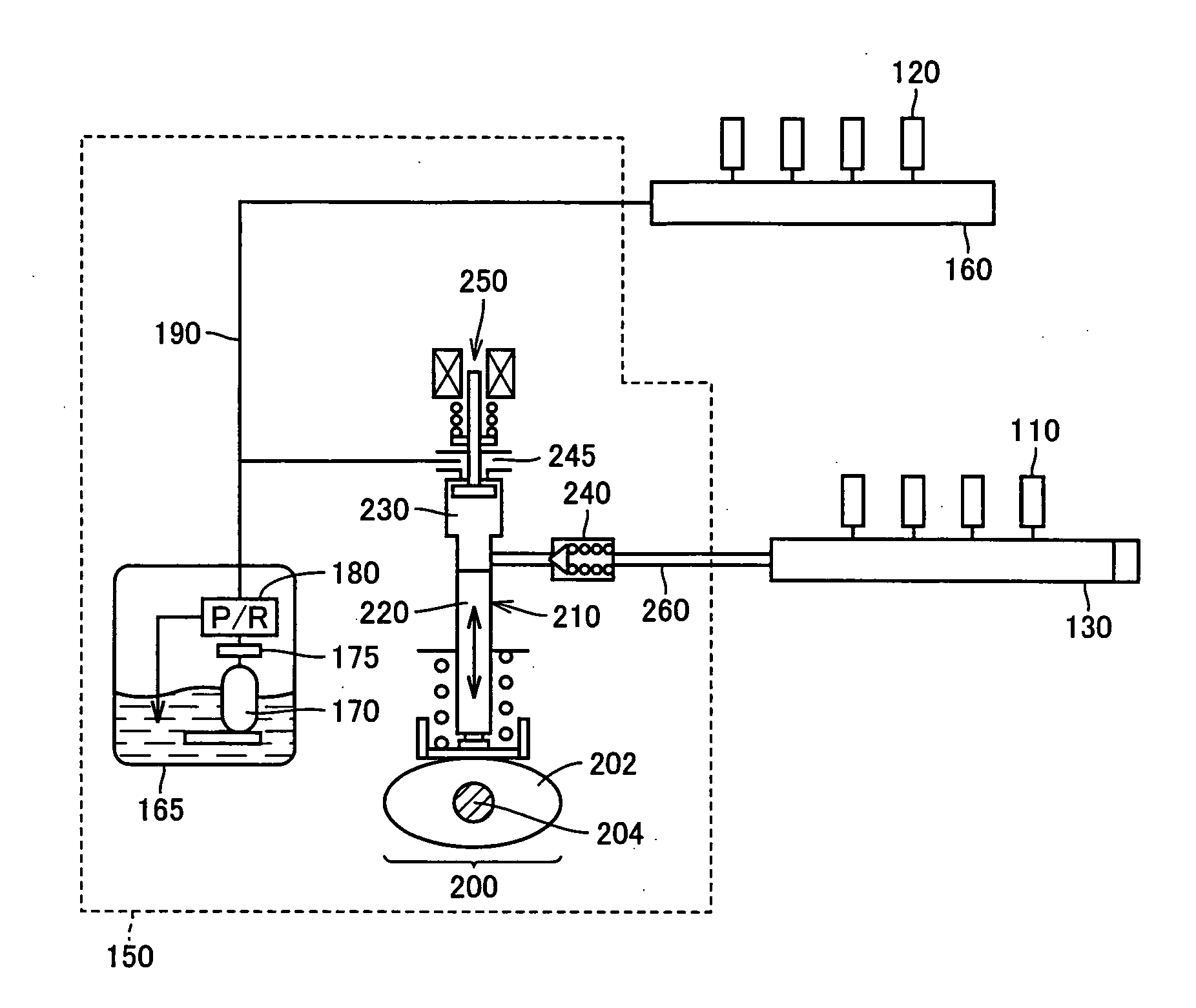
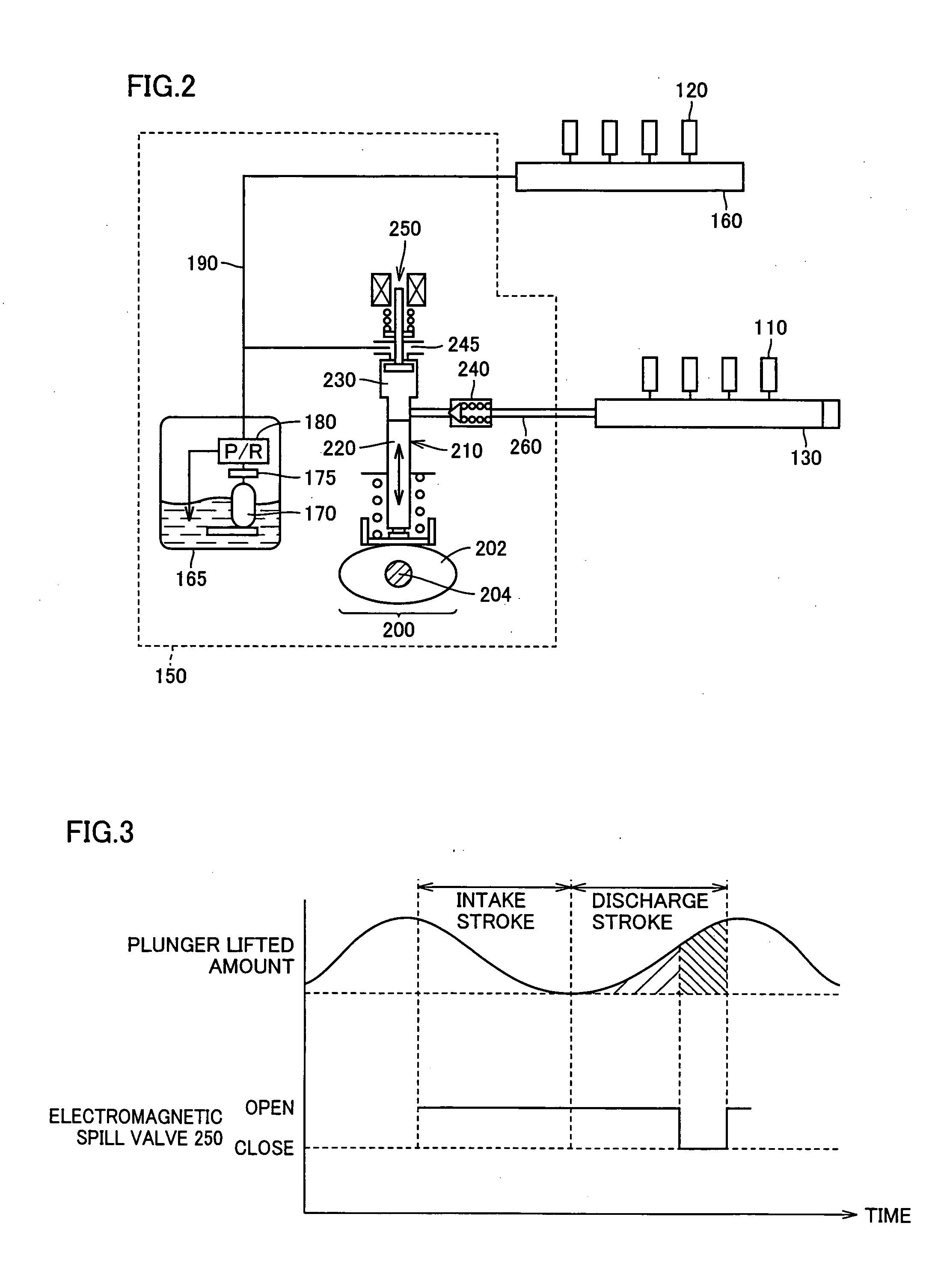
[0103] In the fuel supply apparatus according to the first embodiment, low-pressure fuel pump 170 is shared by the low-pressure fuel supply system and the high-pressure fuel supply system, and the fuel once drawn by high-pressure fuel pump 200 is discharged back to low-pressure fuel path 190 during the valve-opening period of electromagnetic spill valve 250, which may cause variation in fuel pressure in the low-pressure fuel system. Thus, in the second embodiment, a configuration capable of preventing such variation in fuel pressure in the low-pressure fuel supply system will be explained.

[0104] Referring to FIGS. 12 and 13, the fuel supply apparatus according to a first configuration example of the second embodiment includes a fuel supply system 151, intake manifold injectors 120 and low-pressure delivery pipes 160a, 160b, and in-cylinder injectors 110 and high-pressure delivery pipes 130a, 130b. In-cylinder injectors 110 are divided into groups and arranged in banks a and b, and ...


PUM


Abstract

An electrically driven type low-pressure fuel pump whose flow rate can be set draws fuel from a fuel tank and discharges it at a prescribed pressure commonly to a low-pressure fuel supply system including intake manifold injectors and a low-pressure delivery pipe and to a high-pressure fuel supply system including in-cylinder injectors, a high-pressure delivery pipe and a high-pressure fuel pump. The discharge flow rate of the low-pressure fuel pump is set based on required supply quantities to the low-pressure fuel supply system and to the high-pressure fuel supply system obtained according to the engine operation conditions. The discharge quantity of the fuel pump in the internal combustion engine can be set as appropriate, and thus, deterioration in fuel efficiency due to excessive flow rate setting and operation failure due to insufficient fuel supply can be prevented, whereby reliability is improved.

Description

[0001] This nonprovisional application is based on Japanese Patent Application No. 2004-334444 filed with the Japan Patent Office on Nov. 18, 2004, the entire contents of which are hereby incorporated by reference. BACKGROUND OF THE INVENTION [0002] 1. Field of the Invention [0003] The present invention relates to a fuel supply apparatus, and more particularly to a fuel supply apparatus for an internal combustion engine having first fuel injection means (in-cylinder injector) for injecting fuel into a cylinder and second fuel injection means (intake manifold injector) for injecting fuel into an intake manifold or an intake port. [0004] 2. Description of the Background Art [0005] A fuel supply apparatus (fuel injection apparatus) provided with an intake manifold injector for injecting fuel into an intake port and an in-cylinder injector for injecting fuel into a cylinder, and controlling the intake manifold injector and the in-cylinder injector in accordance with an operation state t...

Claims


Application Information

Patent Timeline
IPC IPC(8): F02M57/02
CPCF02D33/003F02D41/3854F02M37/0047F02M59/366F02M63/0225F02M63/029F02M69/02F02M69/046F02M69/462F02D41/3094
Inventor FURUSAWA, SHINYATOMODA, TERUTOSHISAKAI, MITSUTOYAMAZAKI, DAICHITSUCHIYA, TOMIHISA
Owner TOYOTA JIDOSHA KK
Why Eureka
Try Eureka