Nanocomposites with high thermoelectric figures of merit

a technology of nanocomposites and thermoelectric figures, applied in the field of nanocomposites with high thermoelectric figures of merit, can solve the problems of low efficiency, low coefficient of performance (cop) (for refrigeration applications), and low efficiency of conventional thermoelectric materials with a small figure of merit, and achieve the effect of reducing the thermal conductivity of the composite and enhancing the thermoelectric properties

Inactive Publication Date: 2006-05-18
TRUSTEES OF BOSTON COLLEGE THE +1
View PDF55 Cites 171 Cited by
  • Summary
  • Abstract
  • Description
  • Claims
  • Application Information

AI Technical Summary

Benefits of technology

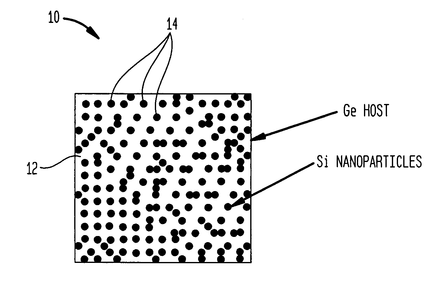
[0005] The present invention is generally directed to nanocomposite thermoelectric materials that exhibit enhanced thermoelectric properties. The nanocomposite materials include two or more components, with at least one of the components forming nano-sized structures within the composite material. The components are chosen such that thermal conductivity of the composite is decreased without substantially dimi

Problems solved by technology

The utility of such conventional thermoelectric devices is, however, typically limited by their low coefficient-of-performance (COP) (for refrigeration applications) or low efficiency (for power generation applications).
Applications of conventional semiconductor thermoelectric coolers are rather limited, as a result of a low figure-of-merit, despite many advant

Method used


Image

  • Nanocomposites with high thermoelectric figures of merit
  • Nanocomposites with high thermoelectric figures of merit
  • Nanocomposites with high thermoelectric figures of merit

Examples


embodiment 34

[0052] Although the segmented nanowires 28 in the above nanocomposite composition 26 are disposed relative to one another in a regular three-dimensional pattern, in another embodiment 34, shown schematically in FIG. 6C, the nanowires 28 are randomly located relative to one another.

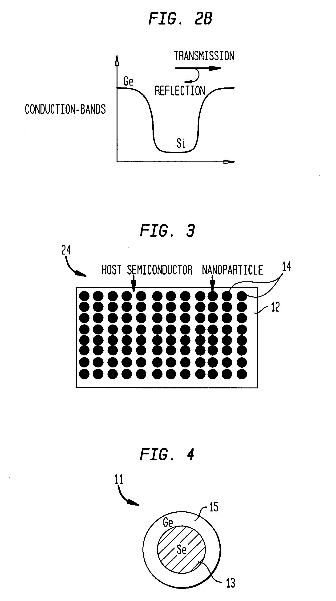
[0053]FIG. 7A schematically illustrates a thermoelectric nanocomposite composition 36 according to another embodiment of the invention that is formed of a plurality of stacked nanowire structures 38, each of which is composed of two nanowires disposed substantially coaxially relative to one another. For example, as shown schematically in FIG. 7B, each nanowire structure 38 can include an outer shell 40 formed of a semiconductor material that surrounds an inner core 42, which is formed of another semiconductor material. The coaxial nanowire 38 can have a cross-sectional diameter D in a range of about 1 nm to about 1 micron, or in a range of about 1 nm to about 300 nm, and more preferably in a range of about...

embodiment 44

[0056] Although in the above thermoelectric composition the nanowire structures include two layers—an inner core surrounded by an outer shell—in other embodiments, more than two layers, e.g., two coaxially disposed shells surrounding an inner core, can be employed. Further, although the coaxial nanowires 38 in the above composition 36 are disposed randomly relative to one another, in another embodiment 44, shown schematically in FIG. 8, the coaxial nanowires are arrange relative to one another according to a three-dimensional pattern.

[0057] A variety of techniques can be employed to fabricate thermoelectric nanocomposite compositions according to the teachings of the invention, such as those described above. In general, known techniques, such as, wet chemistry techniques and vapor-liquid-solid condensation, can be utilized to generate the nanostructures, e.g., nanoparticles or nanowires. These nanostructures are preferably incorporated within a host material, or intermixed with one ...


PUM

PropertyMeasurementUnit
Pressureaaaaaaaaaa
Diameteraaaaaaaaaa
Diameteraaaaaaaaaa

Abstract

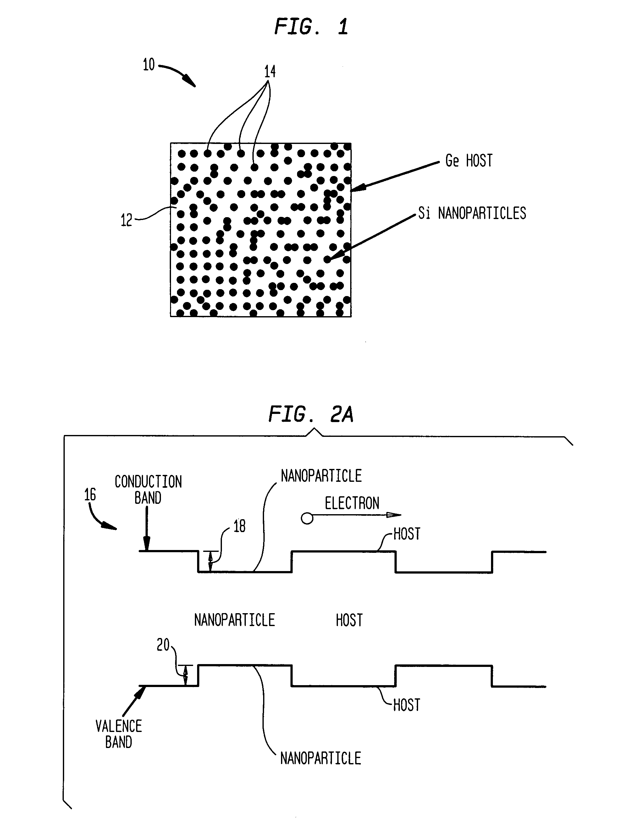
The present invention is generally directed to nanocomposite thermoelectric materials that exhibit enhanced thermoelectric properties. The nanocomposite materials include two or more components, with at least one of the components forming nano-sized structures within the composite material. The components are chosen such that thermal conductivity of the composite is decreased without substantially diminishing the composite's electrical conductivity. Suitable component materials exhibit similar electronic band structures. For example, a band-edge gap between at least one of a conduction band or a valence band of one component material and a corresponding band of the other component material at interfaces between the components can be less than about 5 kBT, wherein kB is the Boltzman constant and T is an average temperature of said nanocomposite composition.

Description

BACKGROUND OF THE INVENTION [0001] The present invention is generally directed to thermoelectric materials and methods for their synthesis and, more particularly, to such materials that exhibit enhanced thermoelectric properties. [0002] Solid-state cooling and power generation based on thermoelectric effects are known in the art. For example, semiconductor devices that employ Seebeck effect or Peltier effect for power generation and heat pumping are known. The utility of such conventional thermoelectric devices is, however, typically limited by their low coefficient-of-performance (COP) (for refrigeration applications) or low efficiency (for power generation applications). A thermoelectric figure-of-merit (⁢Z=S2⁢σk, where S is the Seebeck coefficient, σ is the electrical conductivity, and k is thermal conductivity) is typically employed as the indicator of the COP and the efficiency of thermoelectric devices. In some cases, a dimensionless figure-of-merit (ZT) is employed, where T ...

Claims


Application Information

Patent Timeline
IPC IPC(8): H01L35/28
CPCH01L35/16H01L35/22Y10T428/2938Y10S257/00B29C43/36H10N10/852H10N10/855B82Y30/00
Inventor CHEN, GANGREN, ZHIFENGDRESSELHAUS, MILDRED
Owner TRUSTEES OF BOSTON COLLEGE THE
Why Eureka
Try Eureka