
Circuit board structure with embedded selectable passive components and method for fabricating the same

a selectable passive component and circuit board technology, applied in the association of printed circuit non-printed electric components, conductive pattern formation, electrical apparatus construction details, etc., can solve the problems of increasing the overall size of the product incorporating the circuit board, increasing the complexity of the circuit layout and fabrication process of the semiconductor device, and increasing the generation of nois

Active Publication Date: 2006-05-18
PHOENIX PRECISION TECH CORP
View PDF9 Cites 16 Cited by
  • Summary
  • Abstract
  • Description
  • Claims
  • Application Information

AI Technical Summary

Benefits of technology

[0010] In light of the above prior-art drawbacks, a primary objective of the present invention is to provide a circuit board structure with embedded selectable passive components and a method for fabricating the same, by which a designer is able to adjust a set of passive components according to the practical requirements of the current electrical design.
[0011] Another objective of the present invention is to provide a circuit board structure with embedded selectable passive components and a method for fabricating the same, which uses a simple fabrication processes to achieve a set of passive components required by an electrical design.
[0012] A further objective of the present invention is to provide a circuit board structure with embedded selectable passive components and a method for fabricating the same for eliminating the prior-art drawbacks that in case different electrical characteristics such as capacitance, resistance or inductance are required, the multi-layer circuit board needs to be re-designed and re-laminated which significantly increases fabrication costs, materials management difficulty, and the cost of material stocks.
[0015] In response to passive components required by different electrical designs, a conductive layer is optionally applied between the circuit structure and the electrical connection that is electrically connected to the passive components to form electrical connection of the passive components embedded in the circuit board, so that the set structure of the desirable passive components can be simplified. Additionally, a plurality of plated through holes may be formed to electrically connect the circuit structures on the upper and lower surfaces and laminations of the circuit board, in order to further provide flexibility in altering the electrical design.

Problems solved by technology

In accordance with the high integration of the semiconductor device, more leads and circuits are required, thus increasing the generation of noise.
However, this arrangement requires a relatively large circuit board and undesirably increases the overall size of the product incorporating the circuit board.
Moreover, the passive components mounted on the circuit board also increases the complexity of the circuit layout and fabrication processes for the semiconductor device.
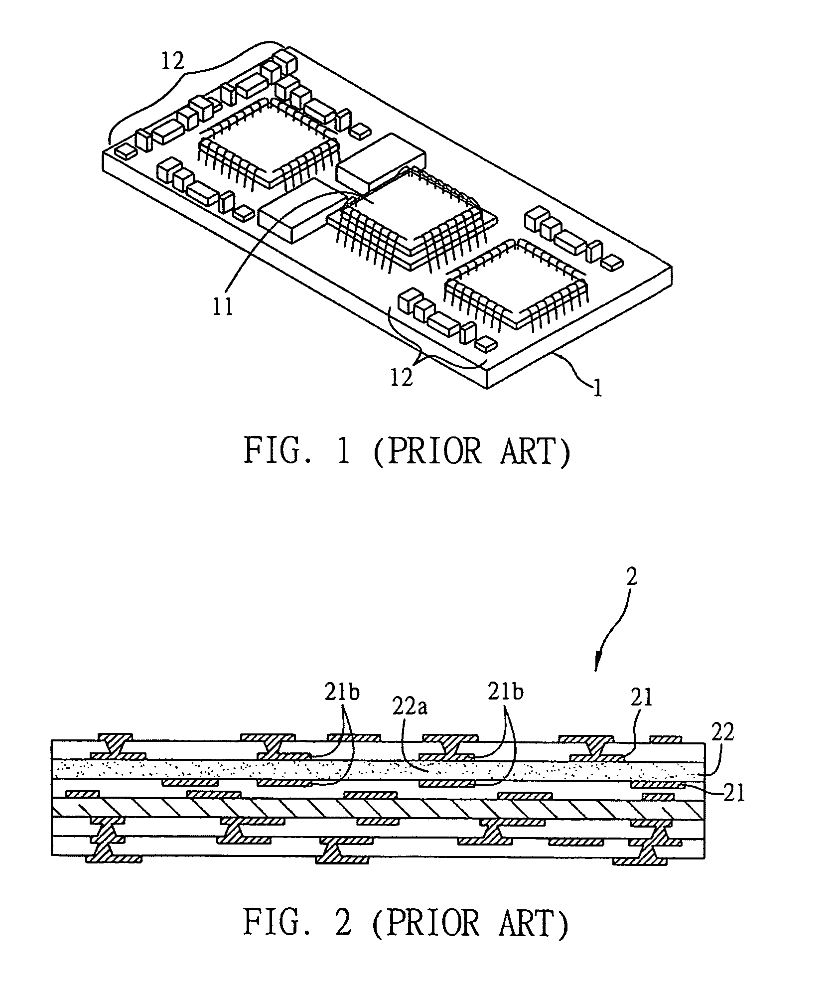
However, considering the space and specific locations required for the bond pads, the number of and mounting locations for passive components 12 is undesirably restricted.
However, although embedding films of passive components between laminations of the multi-layer circuit board is capable of solving the aforementioned problem that restricts trace routability of the circuit board, it still has a drawback.
Since the passive components are disposed between laminations of the circuit board, in cases where different electrical characteristics such as capacitance, resistance or inductance are required, the multi-layer circuit board needs to be re-designed and re-laminated, which significantly increases fabrication costs and causes difficulty in managing material stocks.

Method used


Image

  • Circuit board structure with embedded selectable passive components and method for fabricating the same
  • Circuit board structure with embedded selectable passive components and method for fabricating the same
  • Circuit board structure with embedded selectable passive components and method for fabricating the same

Examples


Embodiment Construction

[0022] The following special embodiment is provided to illustrate the present invention. Other advantages and effects can be understood by those in the art after reading the disclosure of this specification. The present invention can also be performed or applied by other embodiments. The details of the specification are provided using a particular application, and numerous modifications and variations can be devised without departing from the spirit of the present invention. It should be noted that the drawings of the present invention are simplified for the sake of easy illustration and are not drawn according to actual dimensions, and, therefore, do not show the real sizes or relative distances of the associated components.

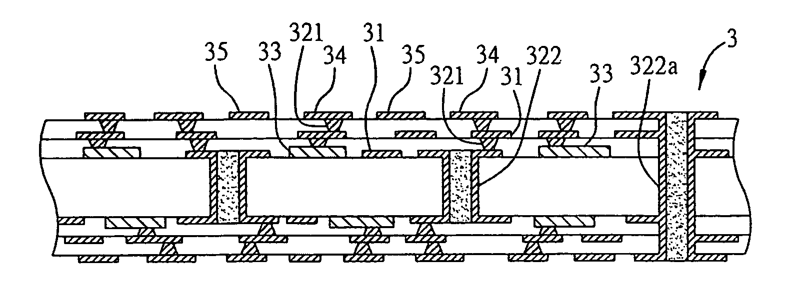
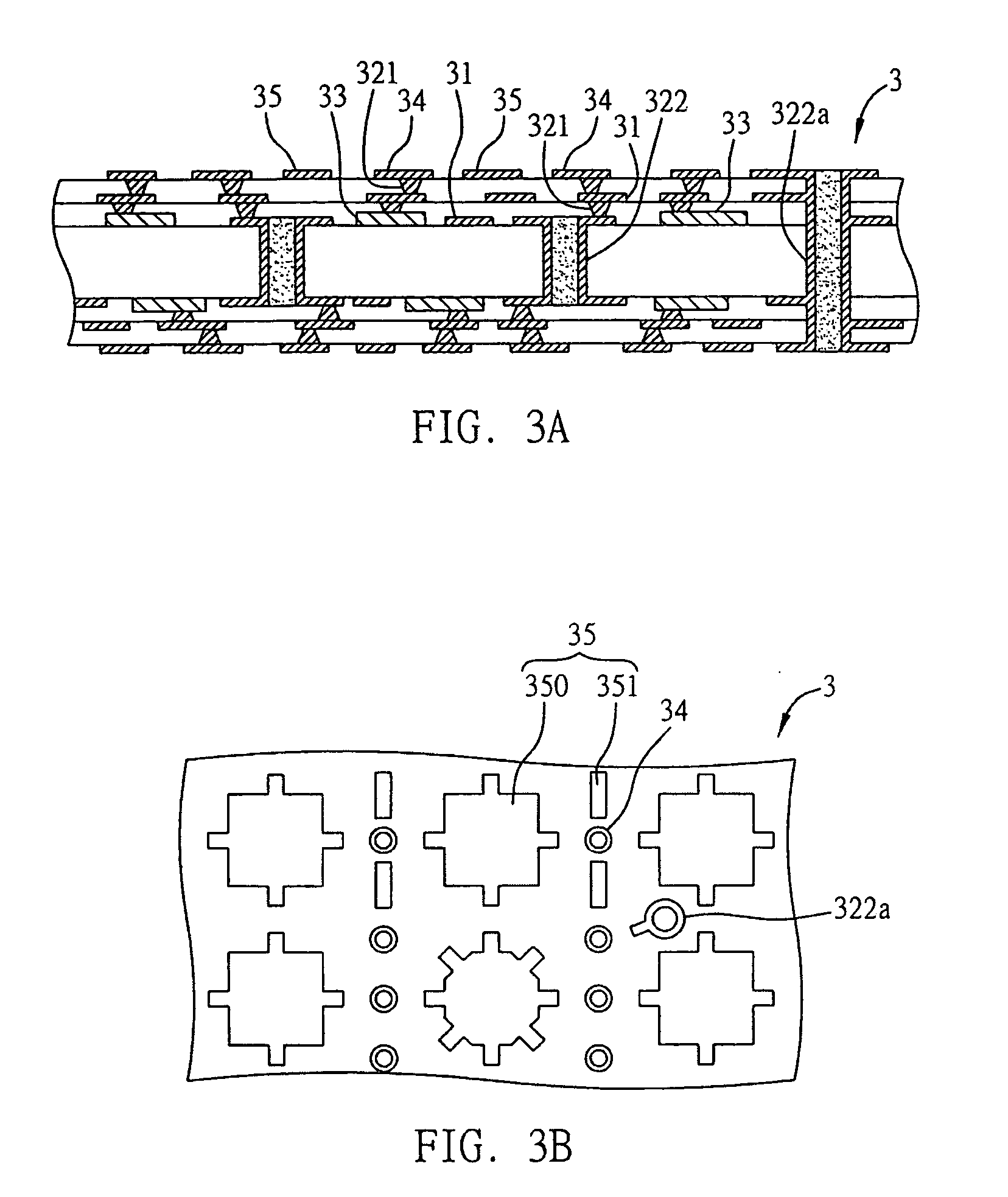
[0023]FIGS. 3A, 3B and FIG. 4 are schematic diagrams showing the method for fabricating the circuit board structure with embedded selectable passive components.

[0024] As shown in FIG. 3A, a multi-layer circuit board 3 is provided. The circuit board 3 includes ...


PUM

PropertyMeasurementUnit
dielectric constantaaaaaaaaaa
conductiveaaaaaaaaaa
electricallyaaaaaaaaaa

Abstract

A circuit board structure with embedded selectable passive components and a method for fabricating the same are proposed, wherein a plurality of passive components are embedded in a circuit board and a plurality of electrical connections are formed on a surface of the circuit board and electrically connected to the passive components. A circuit structure is formed close to the electrical connections for selectively forming a conductive layer thereon to electrically connect a portion of the passive components according to different electrical situations, in order to provide a set of passive components for electrical design of electronic devices.

Description

FIELD OF THE INVENTION [0001] The present invention relates to a circuit board structure with embedded selectable passive components and a method for fabricating the same, and, more particularly, to a circuit board structure and a method for fabricating the same for altering values of resistors, capacitors and / or inductors according to practical requirements of electrical designs. BACKGROUND OF THE INVENTION [0002] Along with the progress of semiconductor packaging technology and improvements in electrical performance of semiconductor chips, semiconductor devices are becoming highly integrated. The traditional lead frame semiconductor device is gradually being replaced with ball grid array (BGA) and a flip chip ball grid array (FCBGA) package structures, wherein a plurality of input / output (I / O) connections are formed on these semiconductor devices for accommodating electronic circuits and semiconductor chips therein. [0003] In accordance with the high integration of the semiconduct...

Claims


Application Information

Patent Timeline
Patent Type & Authority Applications(United States)
IPC IPC(8): H05K1/16
CPCH05K1/029H05K1/0293H05K1/16Y10T29/49155H05K3/4602H05K2203/173H05K1/185
Inventor HSU, SHIH-PING
Owner PHOENIX PRECISION TECH CORP
Learn More