

Narrowband phase difference measurement technique for sonar applications
- Summary
- Abstract
- Description
- Claims
- Application Information
AI Technical Summary
Benefits of technology
Problems solved by technology
Method used
Image

Examples
first embodiment
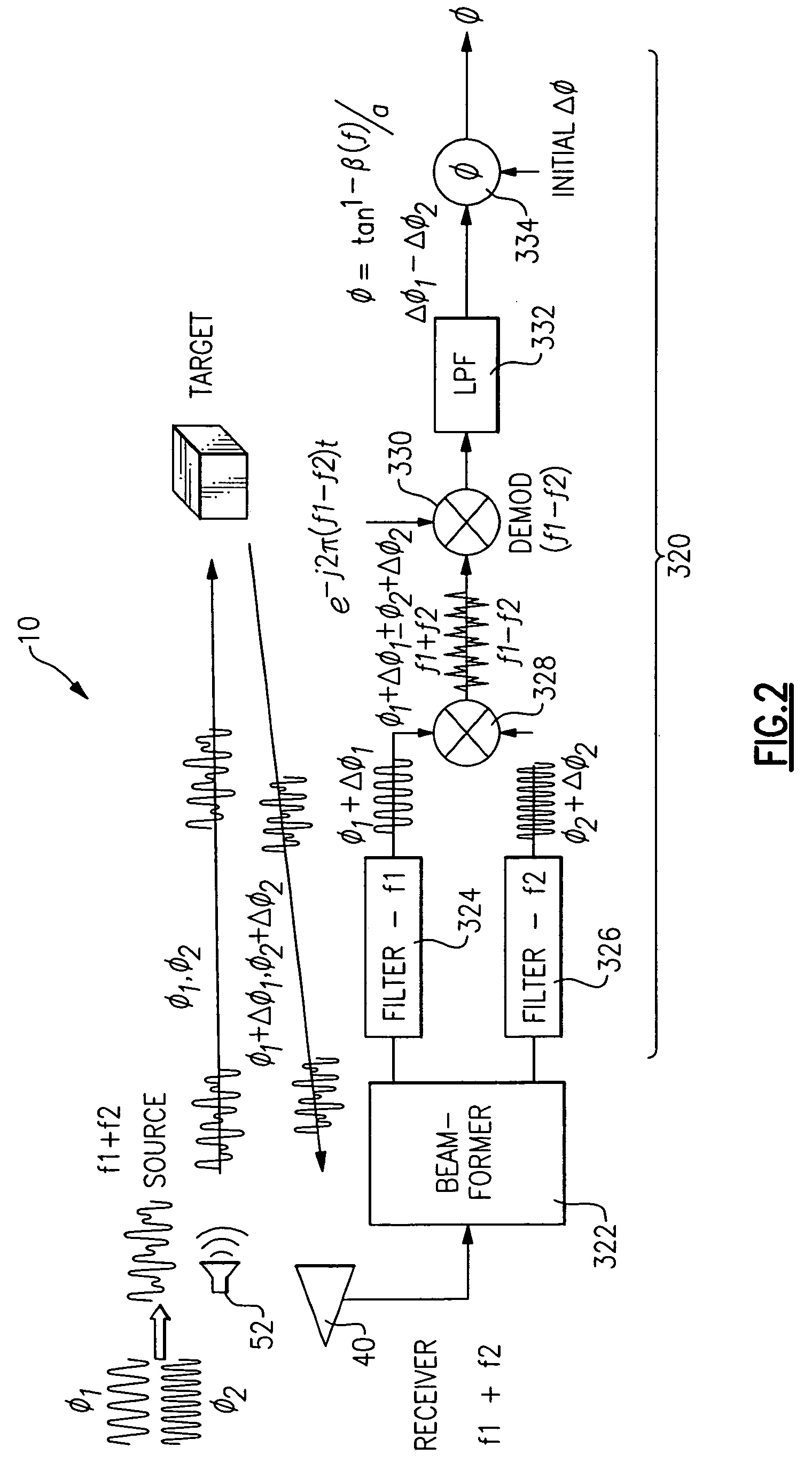
[0037] Referring to FIG. 2, a block diagram of the signal processing flow 320 in accordance with the present invention is disclosed. Sonar transmitter 52 which is configured to actively ping, i.e., direct sonic energy into a propagation channel. The multi-frequency transmit signal is of the form:
T(f)=sin(ω1t+φ1)+sin(ω2t+φ2) (10)
The multi-frequency transit signal propagates in the channel until it is reflected off the target, as shown in FIG. 2. The reflection causes a phase shift to occur. As described above in great detail, the phase shift is a function of the material composition of the target. The multi-frequency received signal is of the form:
R(f)=sin(ω1t+φ1+Δφ1)+sin(ω2t+φ2+Δφ2) (11)
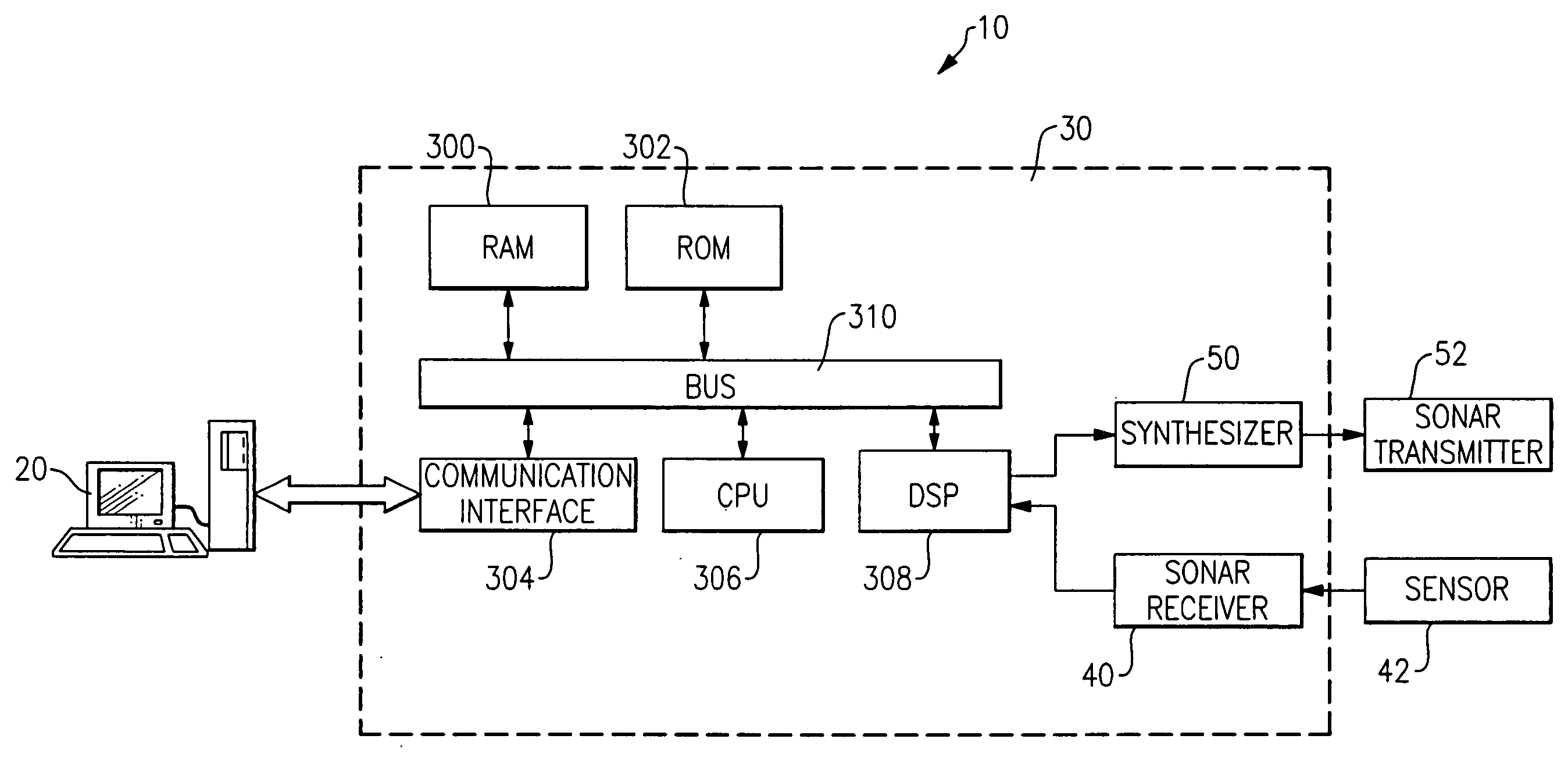
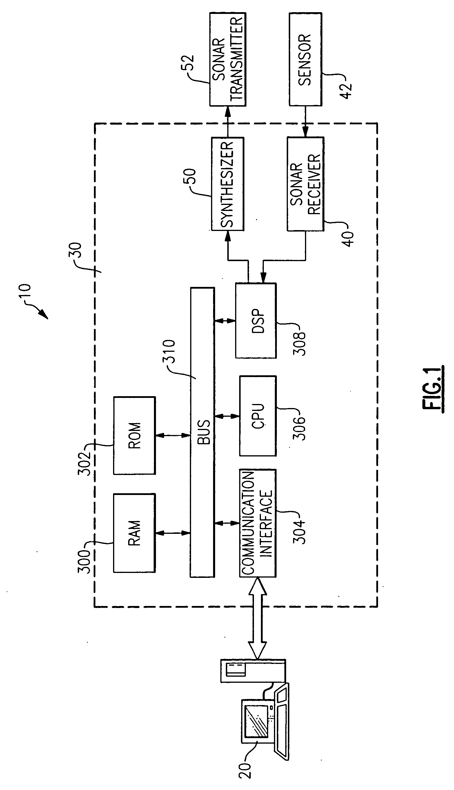
The receiver 40 obtains R(f) from the hydrophonic sensor element 42 as shown in FIG. 2. Receiver 40 typical includes a pre-amplifier and filter coupled to the hydrophonic sensor element 42. The received signal is directed into an A / D / converter and digitized. The digitized signal is directed ...
second embodiment
[0043] As embodied herein and depicted in FIG. 4, a block diagram of a sonar system in accordance with the present invention is disclosed. While the embodiment shown in FIG. 2 processes the return signal in the time-domain, the embodiment depicted in FIG. 4 represents a frequency-domain processing approach.
[0044] As noted above, the multi-frequency received signal is of the form of equation (11). The receiver 40 obtains R(f) from the hydrophonic sensor element 42 as shown in FIG. 4. Receiver 40 typical includes a pre-amplifier and filter coupled to the hydrophonic sensor element 42. The received signal is directed into an A / D / converter and digitized. The digitized signal is directed into beam former 322. Beam forming is a type of spatial filtering that is configured to distinguish the spatial properties of a return signal from noise and / or interference. A digitized version of the signal characterized by equation (11) is directed into Fast Fourier Transform (FFT) module 342. At this ...
PUM
 Abstract
Description
Claims
Application Information