Coated armor system and process for making the same

a technology of armor system and coating, applied in the field of armor system, can solve the problems of difficult to create a structure capable, difficult to meet the requirements of armor, and the methods developed to date are not without their problems

Inactive Publication Date: 2006-05-18
BATTELLE ENERGY ALLIANCE LLC
View PDF21 Cites 27 Cited by
  • Summary
  • Abstract
  • Description
  • Claims
  • Application Information

AI Technical Summary

Benefits of technology

[0006] A method for producing an armor system comprises providing a core material and a stream of atomized coating material that comprises a liquid fraction and a solid fraction. An initial layer is deposited on the core material by positioning the core material in the stream of atomized coating material wherein the solid fraction of the stream of atomized coating material is less

Problems solved by technology

While such multi-layer armoring systems are being used with some degree of success, they are not without their problems.
For example, difficulties are often encountered in creating a structure capable of withstanding multiple projectile impacts.
Another problem relates to the overall

Method used


Image

  • Coated armor system and process for making the same
  • Coated armor system and process for making the same
  • Coated armor system and process for making the same

Examples


example

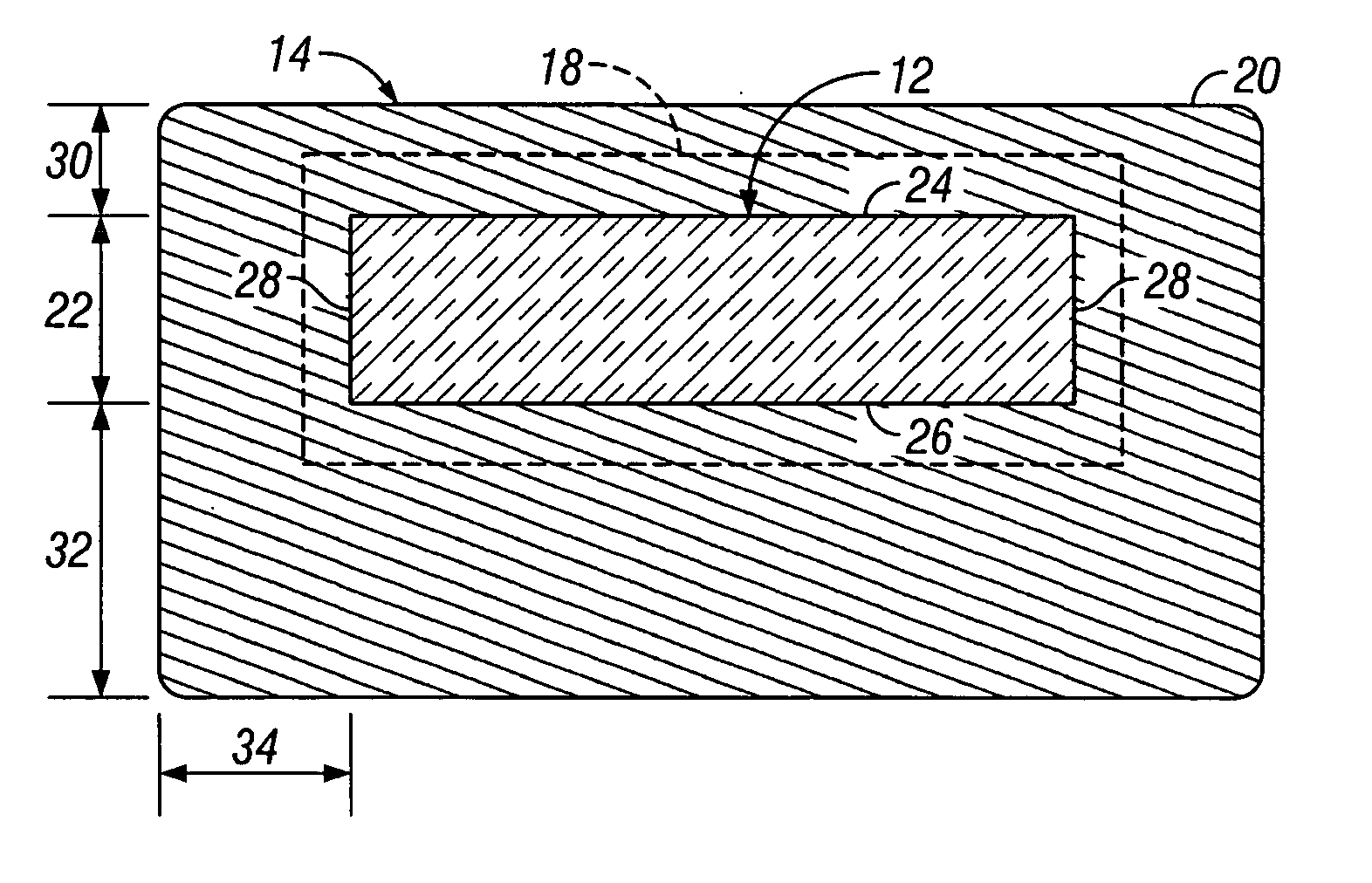
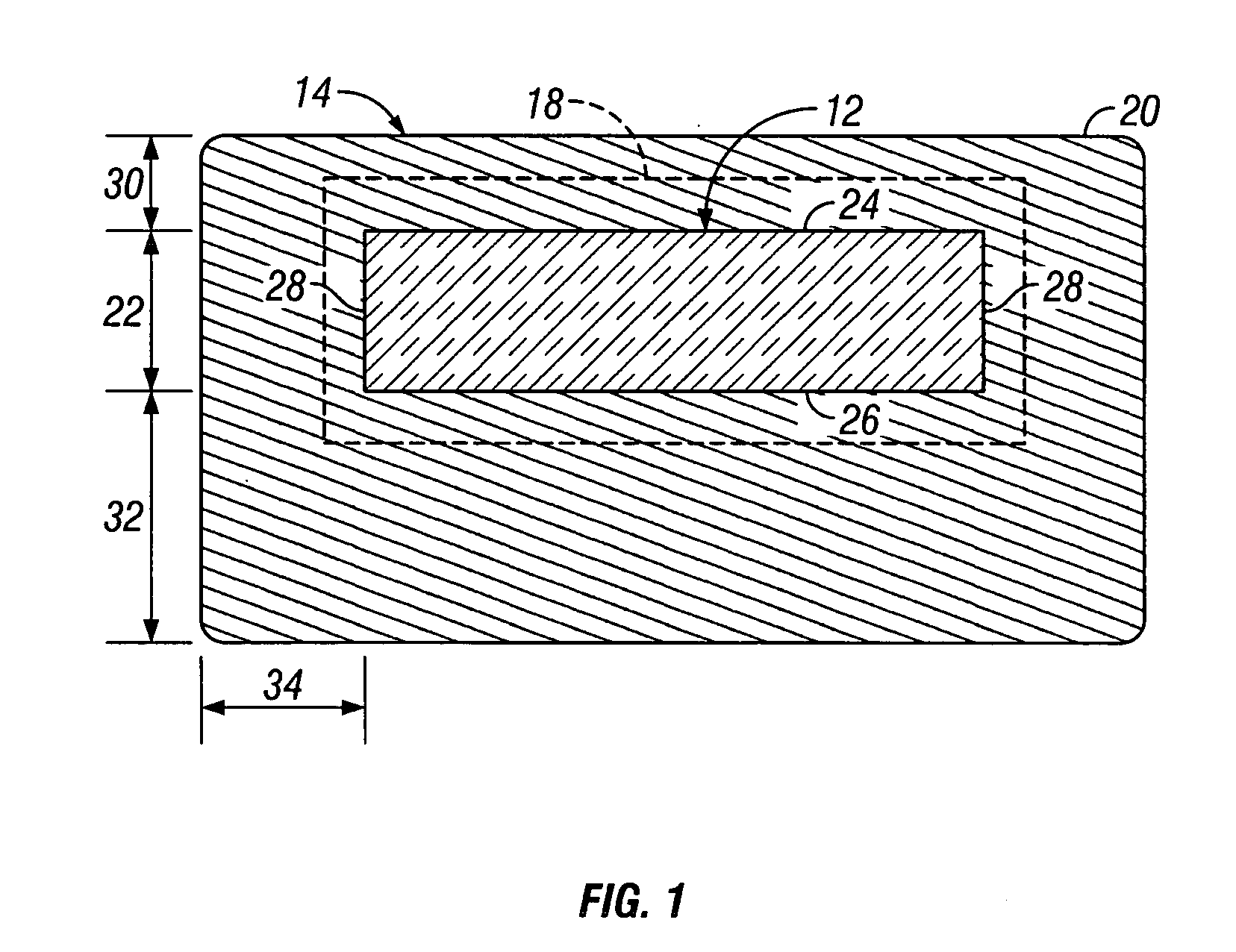
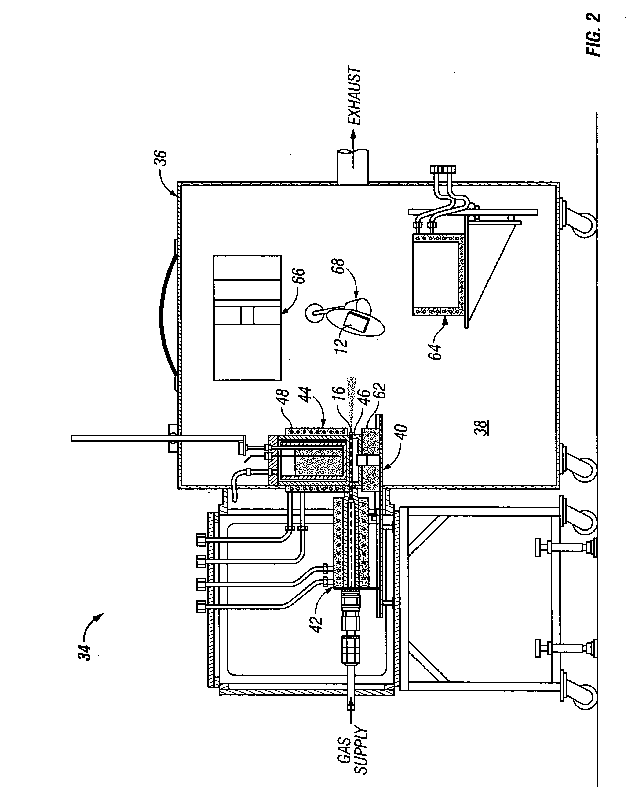
[0063] An armor system 10 according to the present invention was manufactured in accordance with the teachings provided herein. The core material 12 was CoorsTek type AD90 alumina tile. The tile comprised a square configuration having side lengths of about 100 mm and a thickness of about 3.2 mm. The coating material comprised SAE 5083 aluminum alloy. The process chamber 36 was filled with a nitrogen gas atmosphere. The nitrogen gas was introduced into the chamber 36 at about room temperature. The pressure within the chamber 36 was maintained at a pressure of about 100 kPa.

[0064] Molten 5083 aluminum alloy was provided to the coating material feed assembly 44 and maintained at a temperature of about 750° C., which is about 100° C. above the liquidus temperature for the alloy. The atomizing gas comprised nitrogen and was provided to the inlet (i.e., converging section 56) of nozzle 54 at a total temperature of about 700° C. and a total pressure of about 150 kPa. The nitrogen atomized...


PUM

PropertyMeasurementUnit
Fractionaaaaaaaaaa
Fractionaaaaaaaaaa
Thicknessaaaaaaaaaa

Abstract

An armor system and method involves providing a core material and a stream of atomized coating material that comprises a liquid fraction and a solid fraction. An initial layer is deposited on the core material by positioning the core material in the stream of atomized coating material wherein the solid fraction of the stream of atomized coating material is less than the liquid fraction of the stream of atomized coating material on a weight basis. An outer layer is then deposited on the initial layer by positioning the core material in the stream of atomized coating material wherein the solid fraction of the stream of atomized coating material is greater than the liquid fraction of the stream of atomized coating material on a weight basis.

Description

CONTRACTUAL ORIGIN OF THE INVENTION [0001] This invention was made with United States Government support under Contract No. DE-AC07-99ID13727 awarded by the United States Department of Energy. The United States Government has certain rights in the invention.TECHNICAL FIELD [0002] This invention relates to armor systems in general and more specifically to coated armor systems. BACKGROUND [0003] Armor systems are known in the art and are currently being used in a wide range of applications, including, for example, aircraft, armored vehicles, and body armor systems, wherein it is desirable to provide protection against bullets and other projectiles. While early armor systems tended to rely on a single layer of a hard and brittle material, such as a ceramic material, it was soon recognized that the effectiveness of the armor system could be improved considerably if the ceramic material were affixed to or backed-up with an energy-absorbing material, such as fiberglass. The presence of th...

Claims


Application Information

Patent Timeline
IPC IPC(8): C23C16/00B05D3/12B05D3/02B05D1/36
CPCC23C26/00Y10T428/24942Y10T428/2495F41H5/0414Y10T428/31678
Inventor CHU, HENRY S.LILLO, THOMAS M.MCHUGH, KEVIN M.
Owner BATTELLE ENERGY ALLIANCE LLC
Why Eureka
Try Eureka