

Resin Paste For Die Bonding And Its Use
- Summary
- Abstract
- Description
- Claims
- Application Information
AI Technical Summary
Benefits of technology
Problems solved by technology
Method used
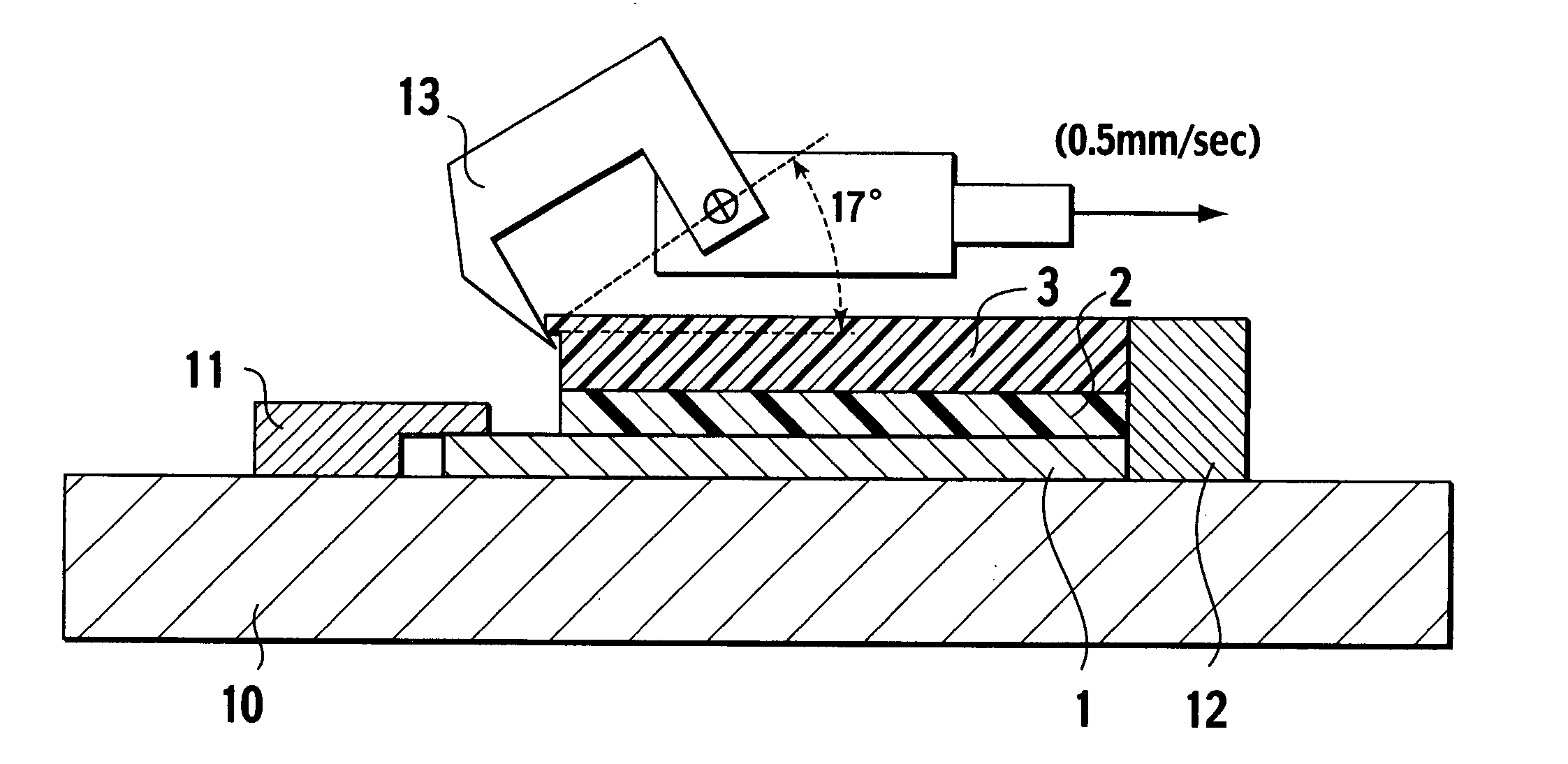
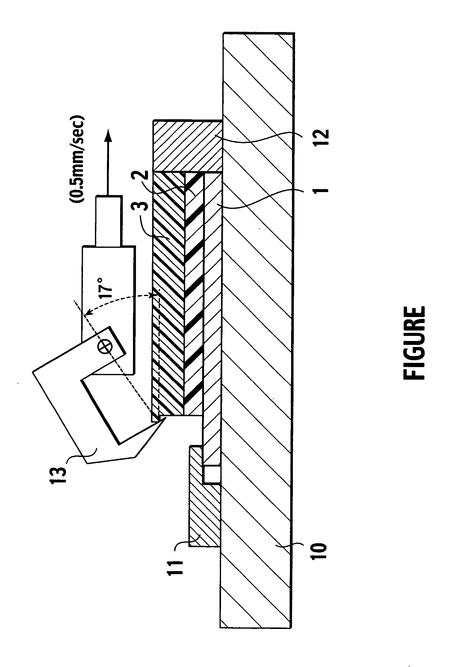
Image

Examples
example 1
[0056] 100 parts by weight of CTBNX-1300×9 (manufactured by Ube Industries, Ltd.) was weighed and placed inside a stone mill as the butadiene homopolymer or copolymer (A) having a carboxylic acid terminal group (the base resin). To this resin were added a previously prepared solution comprising 25 parts by weight of an epoxy resin (YDCH-702) and 15 parts by weight of a phenolic resin (H-1) as the thermosetting resin (B) dissolved in carbitol acetate (60 parts by weight) as the printing solvent (D) (the solid fraction concentration of the thermosetting resin was approximately 40% by weight), and 0.5 parts by weight of a curing accelerator (TPPK), and the resulting composition was mixed. Subsequently, 8 parts by weight of a finely powdered silica Aerosil was added as the filler (C), and the resulting mixture was stirred and kneaded for 1 hour, yielding a resin paste for die bonding (resin paste No. 1; solid fraction: 71.2% by weight).
examples 2 to 5
Comparative Example 1
[0057] The nature and blend quantities of the base resin, thermosetting resin, filler and / or solvent were altered, and preparation was conducted in the same manner as the example 1, yielding a series of resin pastes for die bonding (resin pastes No. 2 through No. 6; solid fractions (in order): 68.3, 72.5, 65.5, 67.3, 44.5% by weight; the resin paste No. 6 was for comparative purposes).
[0058] The respective compositions of these resin pastes are shown in Table 1.
TABLE 1MaterialComparative(The bottom lineExample 1Example 2Example 3Example 4Example 5example 1shows parts byResin pasteResin pasteResin pasteResin pasteResin pasteResin pasteweight )No. 1No. 2No. 3No. 4No. 5No. 6Base resinCTBNX-CTBN-CTBNX-CTBNX-CTBN-—1300x91300x311300x91300x91300x8100100100100100Epoxy resinYDCH-702 25YDCH-702 25ESCN-195 25ESCN-195 39YDCH-702 40ESCN-195 100Phenolic resinH-1 15VH-4170 17H-1 15H-1 21H-1 15H-1 53CuringTPPK 0.5TPPK 1.02P4MHZ 1.02P4MHZ 1.02P4MHZ 1.02P4MHZ 1.0acceleratorFi...
PUM
| Property | Measurement | Unit |
|---|---|---|
| Temperature | aaaaa | aaaaa |
| Percent by mass | aaaaa | aaaaa |
| Pressure | aaaaa | aaaaa |
Abstract
Description
Claims
Application Information